Filter System

a filter system and filter element technology, applied in the field of filters, can solve the problems of clogging of filters, restricting or choking the flow of gas stream, and affecting so as to eliminate improper installation of filters, and facilitate the installation of filters

Inactive Publication Date: 2007-10-04
BHA ALTAIR
View PDF26 Cites 7 Cited by
  • Summary
  • Abstract
  • Description
  • Claims
  • Application Information

AI Technical Summary

Benefits of technology

[0007] The present development is an improvement upon existing filter systems. The present invention is a filter featuring a new sealing design and an assembly to facilitate installation of the filter. In particular, an integral retainer clamp is attached to the filter and a higher sealing bead is added to the filter to not only make installation of the filter easier, but to also reduce, if not eliminate, improper installation of the filter and increase the sealing of the filter. This new design further greatly reduces the labor costs associated with installation of the filter. Specifically, whereas in the past it normally takes two people to install the filter, the filter of the present invention, can be installed by one person.

Problems solved by technology

As the above mentioned baghouses / filtering equipment operate, the particles begin to clog the filters and restrict, or choke, the flow of the gas stream.

Method used


Image

  • Filter System
  • Filter System
  • Filter System

Examples


Embodiment Construction

[0028] While this invention is susceptible of embodiments in many different forms, there is shown in the drawings and will herein be described in detail, preferred embodiments of the invention with the understanding the present disclosure is to be considered as an exemplification of the principles of the invention and is not intended to limit the broad aspect of the invention to the embodiments illustrated. The present invention will have the following main components and techniques for operation of the device.

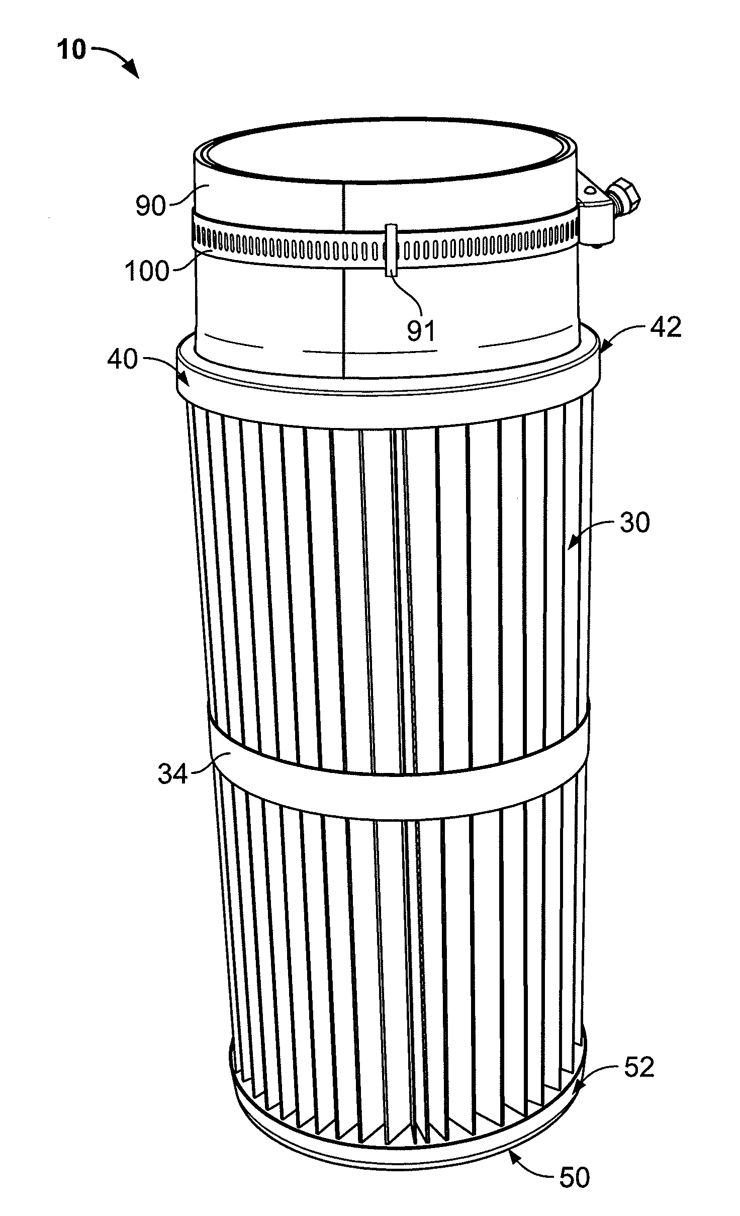
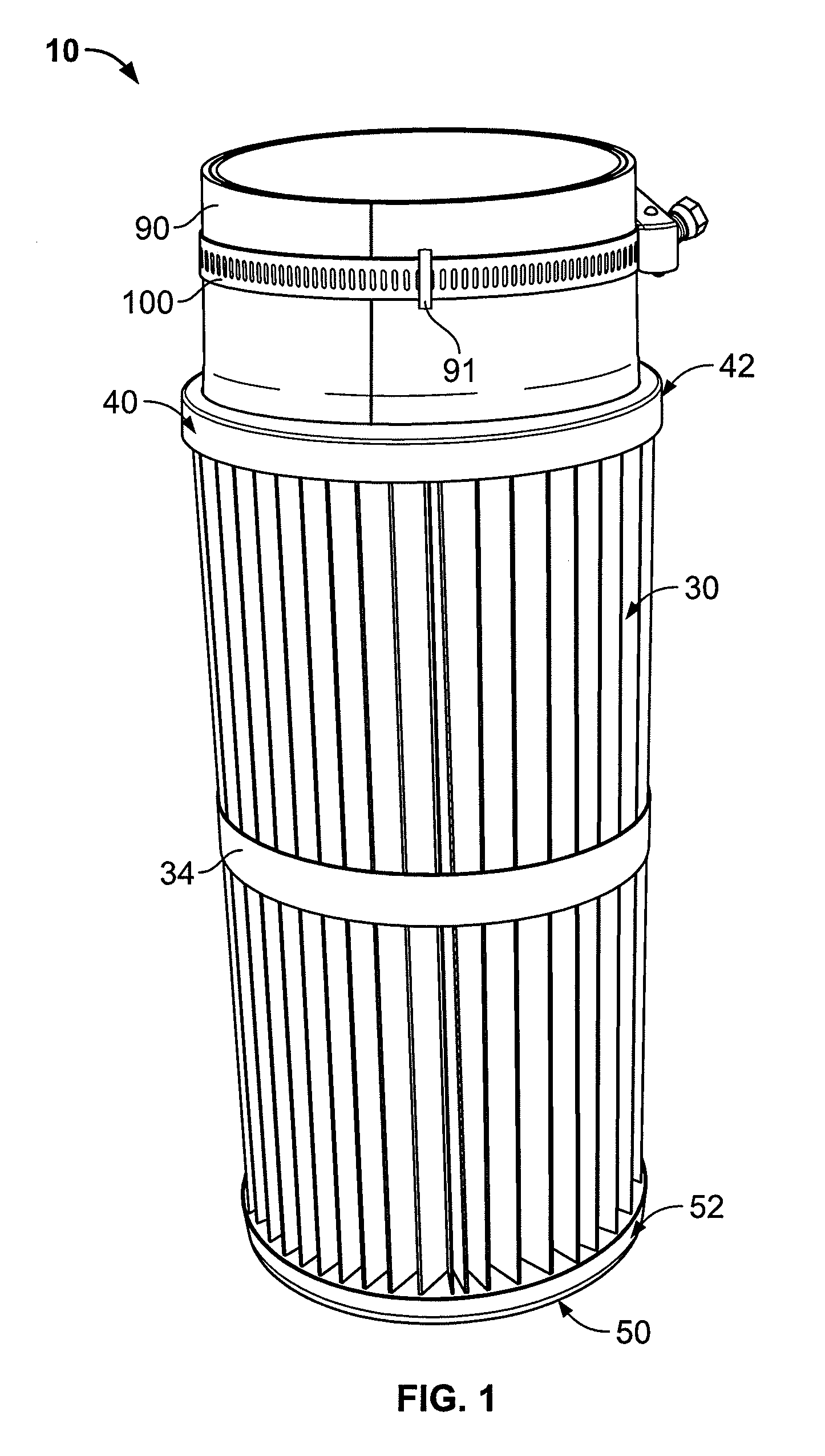
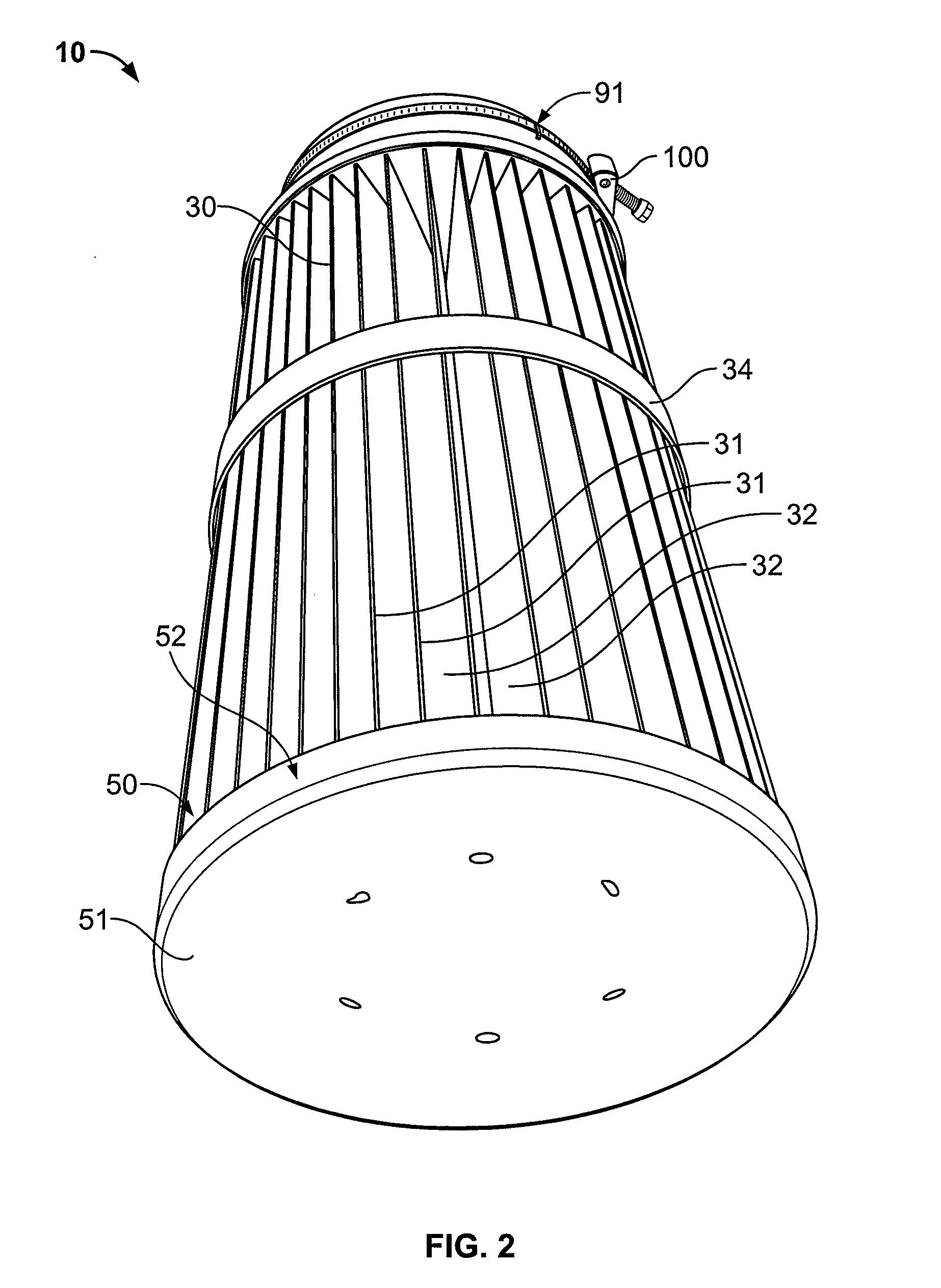
[0029]FIGS. 1-8 show a filter element, designated generally by reference number 10. The filter 10 includes a rigid metal cylindrical screen core 20. The mesh size of the screen 20 is customized to the purpose of the filter 10. As shown in FIG. 7, the core is an open helix configuration. The core 20 is surrounded by a radially projecting pleated filter element 30 (forming ridges 31 and grooves 32) secured between a first end cap 40 and second end cap 50. The screen 20 is also ...


PUM

PropertyMeasurementUnit
inner radiusaaaaaaaaaa
inside radiusaaaaaaaaaa
depthaaaaaaaaaa

Abstract

A filter element (10) is disclosed having a integral clamp (100) thereon. The adjustable clamp (100) is held against a sleeve (90) by attached tabs (91). The sleeve (90) covers a collar (70) with a plurality of fingers (72) thereon. A high head, e.g., the apex, formed by a bead (80) in the fingers (72) permits better sealing between the filter (10) and the filter's support housing.

Description

RELATED APPLICATION [0001] This Application claims the benefit of Provisional Patent Application Ser. No. 60 / 787,007 filed Mar. 29, 2006.TECHNICAL FIELD [0002] The present invention relates to filters, and more particularly, to a bottom load baghouse filter element. BACKGROUND OF THE INVENTION [0003] Industrial facilities often discharge particle or dust laden exhaust. Consequently, government regulations and standards regulate such exhaust. As a result, particle / dust collection or recovery systems, such as baghouses and cyclone separators, are used for the removal of the particles and dust before further processing of the exhaust, if necessary, and release to the atmosphere. For example, while baghouses remove particulate from the gas stream, the exhaust may also need to be treated to remove other non-particulate dangers such as sulfur dioxide, nitrogen oxides, volatile organic compounds, and carbon monoxide. The dust and gas conveyed to a baghouse or other similar air or gas filte...

Claims


Application Information

Patent Timeline
Patent Type & Authority Applications(United States)
IPC IPC(8): B01D46/00
CPCB01D46/0004B01D46/521B01D46/02B01D46/0005
Inventor MODESTO, DANIEL
Owner BHA ALTAIR
Why Eureka
Try Eureka