
Method for the Preparation of Y-Branched Carbon Nanotubes

a carbon nanotube and y-junction technology, applied in chemical/physical/physical-chemical processes, chemical apparatus and processes, energy-based chemical/physical/physical-chemical processes, etc., can solve the problem of limitation in the synthesizing of y-junction carbon nanotubes

Inactive Publication Date: 2007-09-27
KH CHEM CO LTD
View PDF8 Cites 22 Cited by
  • Summary
  • Abstract
  • Description
  • Claims
  • Application Information

AI Technical Summary

Benefits of technology

[0025] In the impregnation method among the foregoing methods, metal precursors are dissolved in a solution, carbon nanotubes are impregnated in the solution, and then the solvent is evaporated or removed to deposit the catalyst as small particles on the surface of carbon nanotube. The method is used generally for loading a catalyst on a carrier, and the composition of catalyst can be modified easily through the treatment of oxidation, reduction, pre-nitriding or pre-sulfiding after loading. On the other hand, other said methods except impregnation are to deposit the catalyst on the surface of carbon nanotubes under the state wherein the chemical composition or property of catalyst is already determined. Although there is a slight difference from each other methods in terms, these two methods can be used alike as a general method to deposit catalytic metals or metal compounds on the surface of carbon nanotubes.

Problems solved by technology

However, these methods are to synthesize one dimensional carbon nanotubes in the shape of tube or rod and have limitations in synthesizing Y-branched carbon nanotubes with Y-junction structure.
However, these results have merely confirmed that most of the products were the wire shaped one dimensional carbon nanotubes and a quite small quantity of two dimensional carbon nanotubes was produced.

Method used


Image

  • Method for the Preparation of Y-Branched Carbon Nanotubes
  • Method for the Preparation of Y-Branched Carbon Nanotubes
  • Method for the Preparation of Y-Branched Carbon Nanotubes

Examples


example 1

[0051] (1) Preparation of Catalyst-Loaded One Dimensional Carbon Nanotubes

[0052]1.81 g of Fe(NO3)39H2O was loaded on 10 g of multi-wall carbon nanotubes with 20 m2 / g of surface area and 60 nm in diameter [prepared as described in WO03 / 008331] by impregnation and then dried at 110° C. for 12 hours or longer.

[0053] The obtained carbon nanotubes loaded with Fe(NO3)39H2O were reduced for 3 hours with flowing hydrogen gas at 600° C. During the process of reduction, the carbon nanotubes used as a carrier were partially destructed through hydrogenation as well as reduction of iron particles and the original carbon nanotubes seemed to be bonded chemically to the newly produced carbon nanotubes. The resulted Fe-loaded carbon nanotubes comprised 2.5 wt % of Fe.

[0054] (2) Preparation of Y-Branched Carbon Nanotubes

[0055] 0.2 g of Fe-loaded one dimensional carbon nanotubes prepared in the above step 1 were put in quartz boat to be positioned at the midst of the quartz tube with 27 mm diamete...

example 2

[0058] (1) Preparation of Catalyst-Loaded One Dimensional Carbon Nanotubes

[0059] Carbon nanotubes loaded with Fe(NO3)39H2O were produced in the same manner as described in Example 1 except that the reduction was not performed.

[0060] (2) Preparation of Y-Branched Carbon Nanotubes

[0061] 0.2 g of carbon nanotubes loaded with Fe(NO3)39H2O prepared in the step (1) were put in quartz boat to be positioned at the midst of the quartz tube with 27 mm diameter in an electric furnace. The reaction temperature in the furnace was elevated to 1000° C. with flowing helium gas at a rate of 100 ml / min. Then, nitrate of ferric nitrate was thermally decomposed to oxidize the surface of carbon nanotubes loaded with ferric nitrate particles and destructed some part of the carbon nanotubes. In this way, iron particles were bonded tightly to carbon nanotubes.

[0062] When the reaction temperature reached 1000° C., hydrogen gas comprising 2 vol % of vaporized benzene was introduced into the reactor for 3...

example 3

[0064] (1) Preparation of Catalyst-Loaded One Dimensional Carbon Nanotubes

[0065] The temperature was elevated to 450° C. while helium gas was flowed on carbon nanotubes loaded with Fe(NO3)39H2O, which were produced in the same manner as described in Example 1. When the temperature reached 450° C., the gas mixture of hydrogen and H2S in the volume ratio of 95:5 was supplied for 2 hours to convert ferric nitrate to be changed to ferrous sulfide (FeS).

[0066] (2) Preparation of Y-Branched Carbon Nanotubes

[0067] 0.2 g of carbon nanotubes loaded with FeS, prepared in the step (1) were put in quartz boat to be positioned at the midst of the quartz tube with 27 mm diameter in an electric furnace. The reaction temperature in the furnace was elevated to 1000° C. with flowing helium gas at a rate of 100 ml / min.

[0068] When the reaction temperature was reached to 100° C., hydrogen gas comprising 2 vol % of vaporized benzene was introduced into the reactor for 30 minutes to produce carbon nan...


PUM


Abstract

The present invention provides a process for preparing Y-branched carbon nanotubes and the product thereby, Y-branched carbon nanotubes. More specifically, the present invention provides a process for preparing Y-branched carbon nanotubes, comprising: loading a catalyst on a carbon nanotube carrier; pre-treating the catalyst-loaded carbon nanotubes to have the catalyst bonded tightly to the surface of carbon nanotubes; and performing a synthetic reaction of carbon nanotubes using the obtained catalyst-loaded carbon nanotubes. According to the process of the present invention, Y-branched carbon nanotubes having at least one or more Y-junctions in various shapes can be prepared easily, simply and in bulk by utilizing the conventional facilities under the usual condition of process. Thus, the invention is promising industrially. The Y-branched carbon nanotubes of the invention holds great potential in regard of materials for electrodes, reinforcing agents for polymers, transistors and electrochemical products.

Description

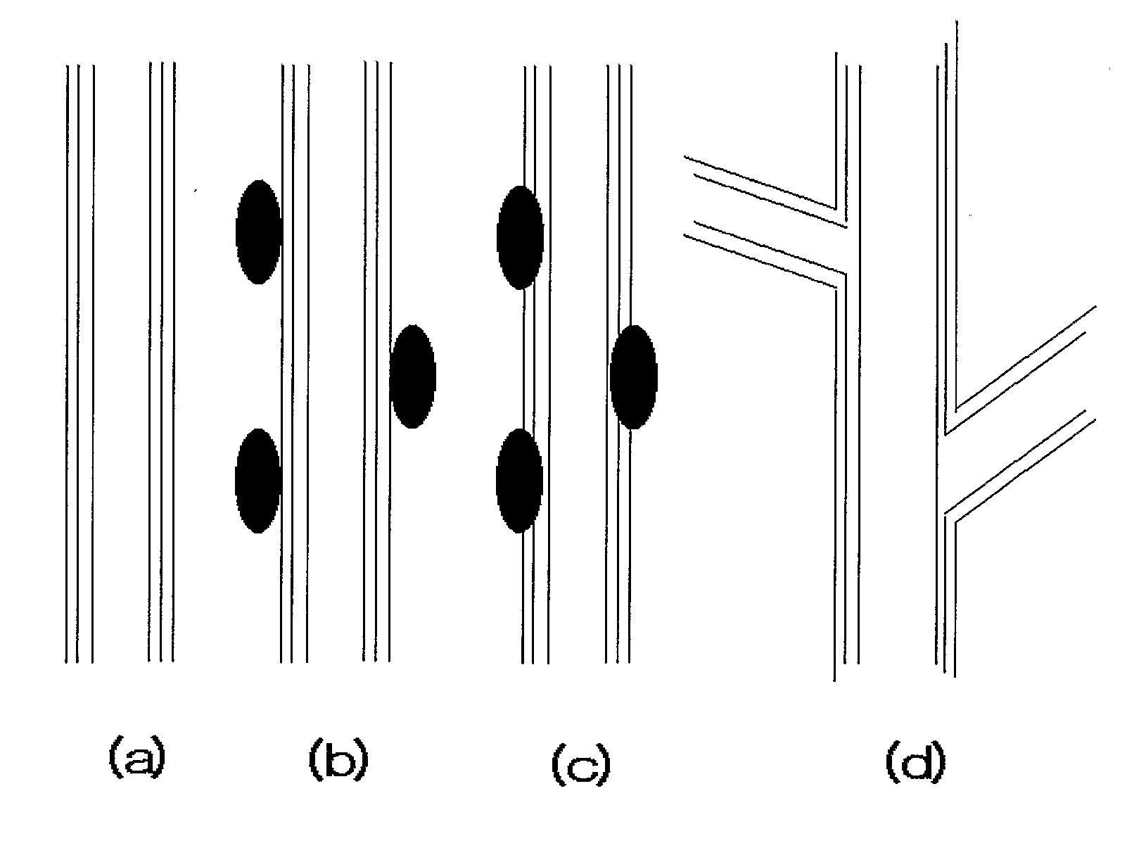
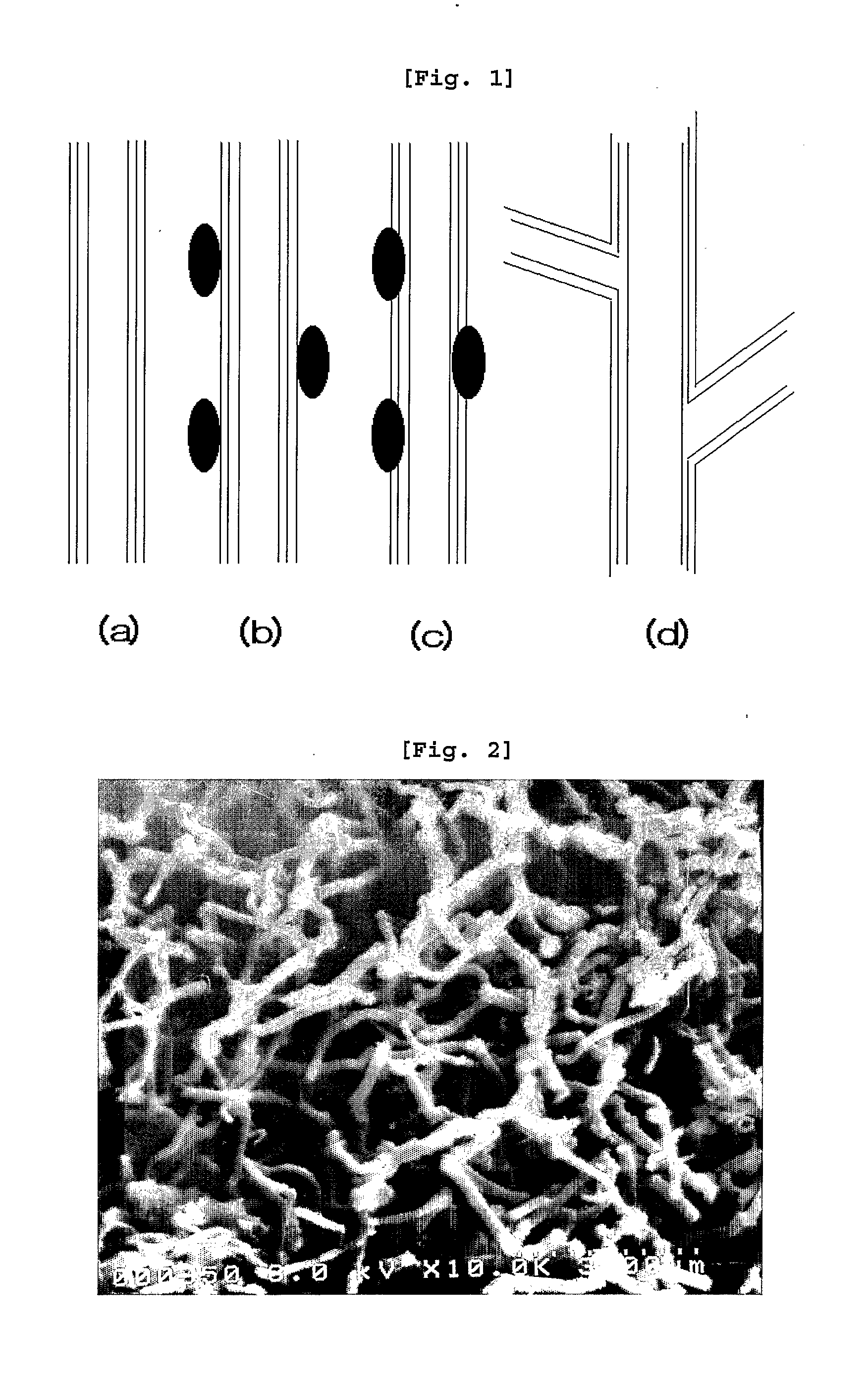
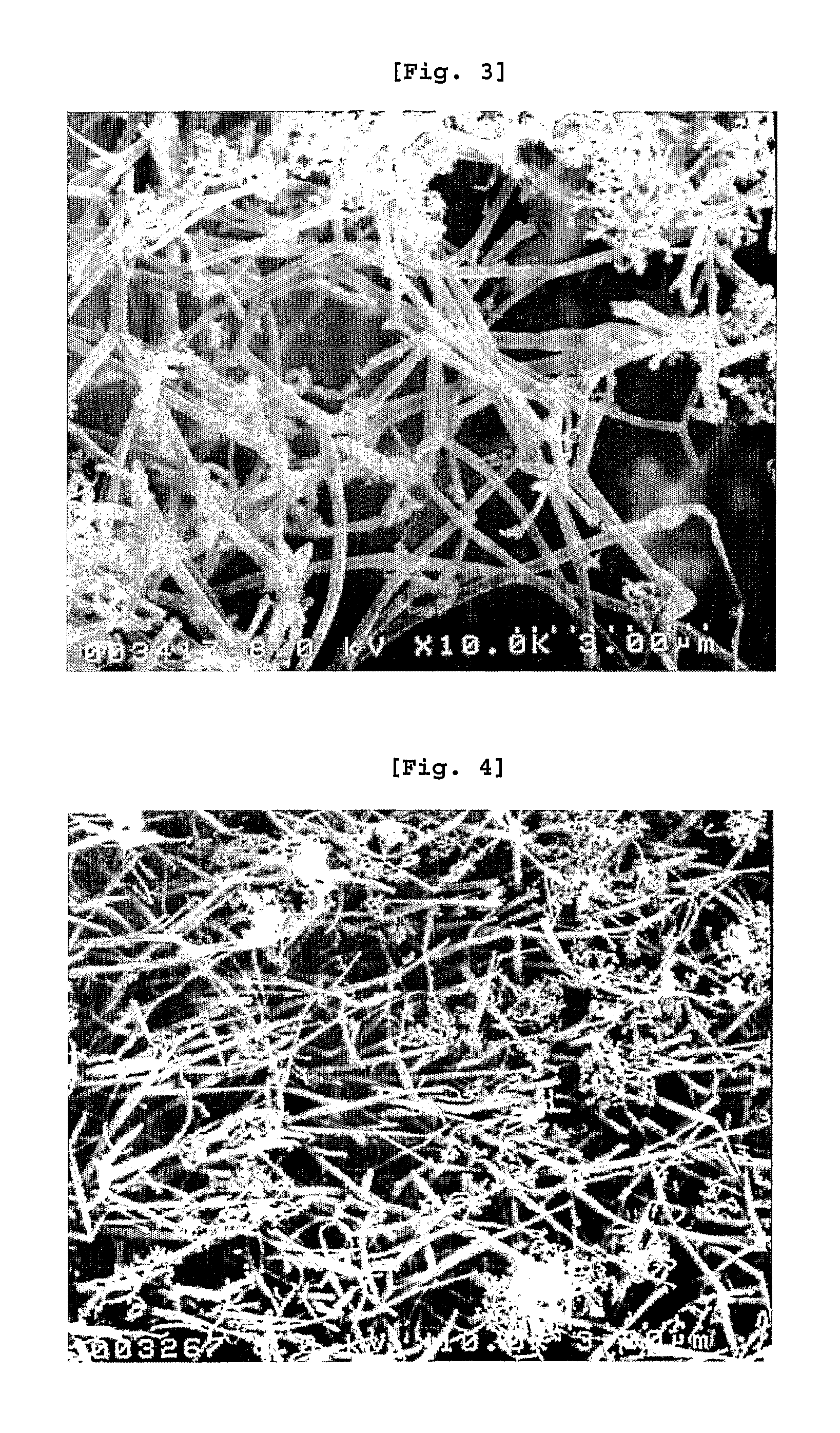
TECHNICAL FIELD AND BACKGROUND ART OF THE INVENTION [0001] This invention relates to a process for preparing Y-branched carbon nanotubes and the product thereby, Y-branched carbon nanotubes. More specifically, the invention concerns Y-branched carbon nanotubes and a process for preparing Y-branched carbon nanotubes comprising the step of: loading a catalyst on a carbon nanotube carrier; pre-treating the catalyst-loaded carbon nanotubes to have the catalyst bonded tightly to the surface of carbon nanotubes; and performing a synthetic reaction of carbon nanotubes using the obtained catalyst-loaded carbon nanotubes. [0002] Carbon nanotubes are substances shaped in cylindrical tubes consisting of carbon atoms, of which a carbon atom is bonded to adjacent three carbon atoms and the bonds between carbon atoms form hexagonal rings repeatedly on a plane in the shape of hives which is rolled up to give the cylindrical tube. [0003] In the past ten years, the study on carbon nanotubes has been...

Claims


Application Information

Patent Timeline
IPC IPC(8): B82B3/00
CPCB82B3/00B82Y30/00B82Y40/00C01B2202/06C01B31/0233C01B2202/00C01B31/022C01B32/162
Inventor KIM, YOUNG NAM
Owner KH CHEM CO LTD
Learn More