
Image Display Unit

a technology of image display and display unit, which is applied in the direction of projectors, instruments, optics, etc., can solve the problems of varying the output position of point light, and achieve the effect of extending the observer's observable rang

Inactive Publication Date: 2007-09-27
SEA PHONE +1
View PDF5 Cites 7 Cited by
  • Summary
  • Abstract
  • Description
  • Claims
  • Application Information

AI Technical Summary

Benefits of technology

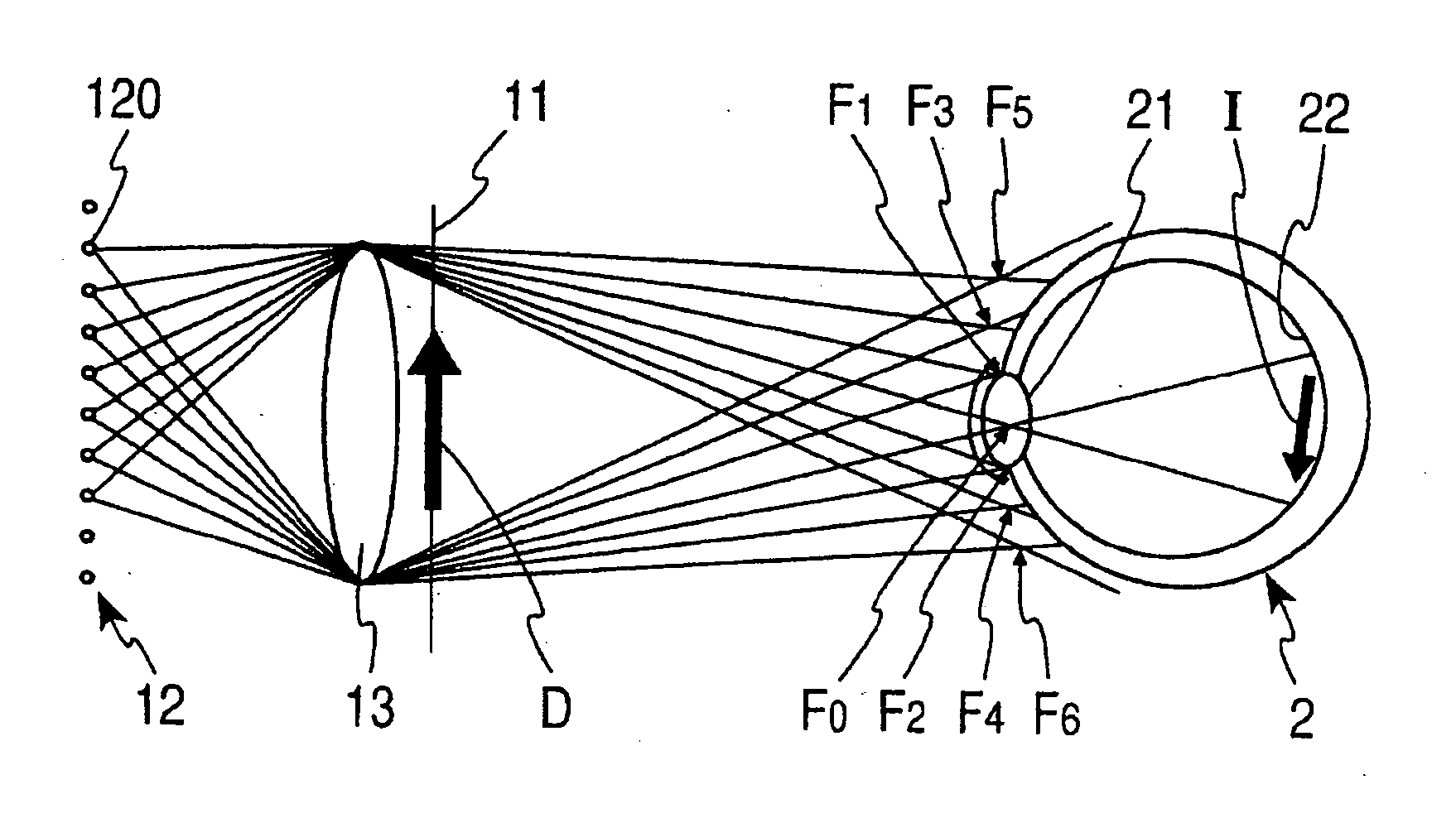
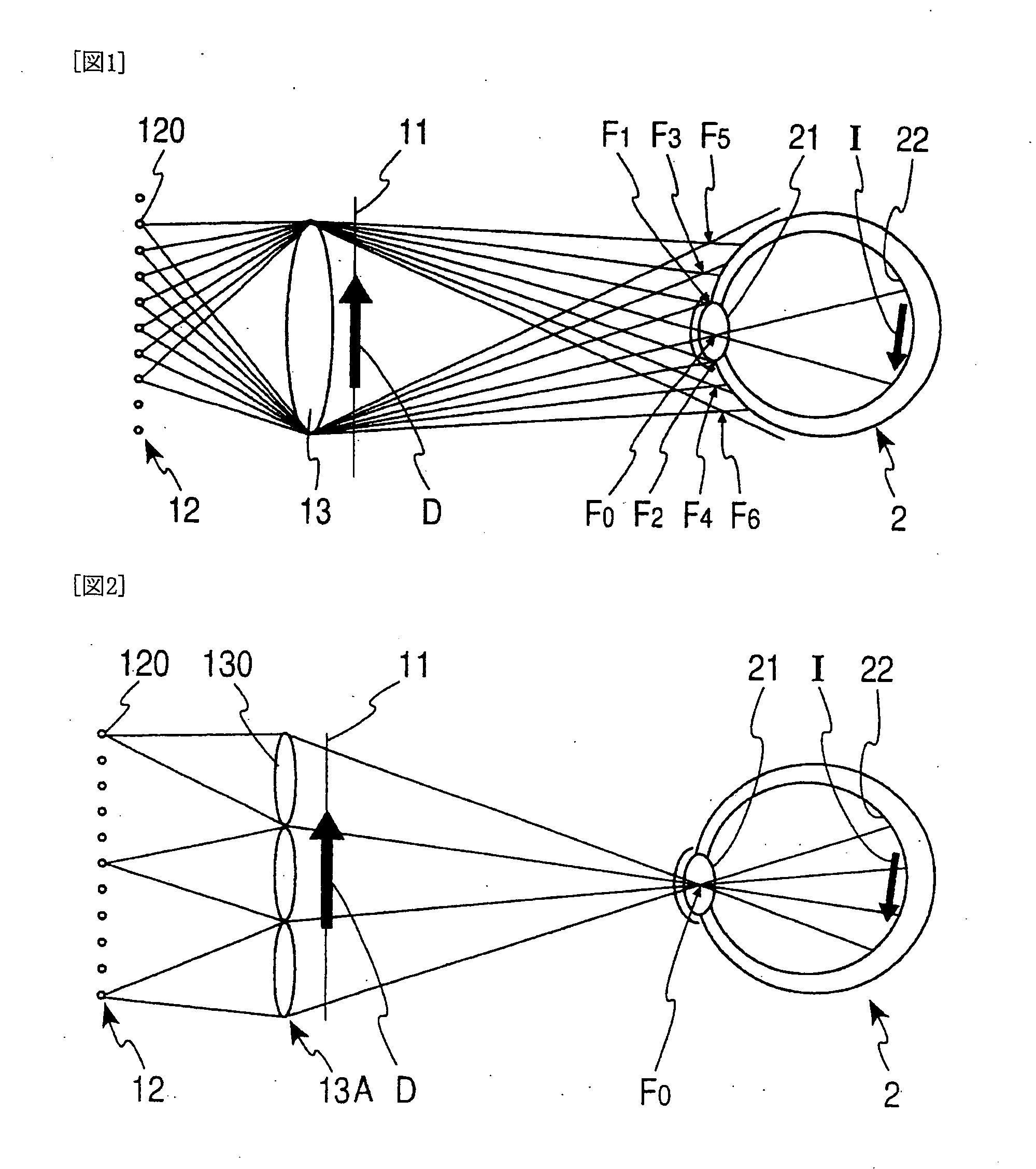
[0007]FIG. 1 and FIG. 2 respectively show the inventive concept of claim 1. Point light sources 120 of a point light source array 12 form images in predetermined positions F0 through F6 by means of image focusing members 13 and 13A. The predetermined positions F0 through F6 are located on an imaginary plane facing the image display unit, but dispersed so as to correspond to the number of the point light sources 120. These drawings show the state when the observer faces the image display unit of the present invention such that a pupil of an eyeball 2 of the observer is located in the position F0 out of the predetermined positions F0 through F6. In this case, light emitted from the point light sources 120 enters a crystalline lens 21 from the pupil of the eyeball 2, and an image D displayed on the transmission type image display plate 11 is projected on a retina 22. Light from the point light sources 120 is converged in substantially one point on the position of the crystalline lens 21 of the eyeball 2 so that the resolution of the image I projected on the retina 22 does not depend on the image focusing ability of the crystalline lens 21. Consequently, the sharpness of the image I is high. Furthermore, the tension of a ciliary body is moderated to decrease eyestrain, which would be caused by a long time viewing of images.
[0032] With this arrangement, even where the distance between the observer and the image display unit varies, the adjustment is carried out to focus images of the point light source on the pupil of the observer, and to further increase the density of the point light sources as long as no double image is displayed on the liquid crystal display plate 3, which is viewed by the observer, and consequently, the observable range by the observer is enlarged frontward and rearward, whereby a much convenient image display unit is obtained. Fourth Embodiment

Problems solved by technology

However, the technique of Patent document 1 requires means for specifying the position of the observer's pupil and varying the point light output position so as to become complicated.

Method used


Image

  • Image Display Unit
  • Image Display Unit
  • Image Display Unit

Examples


first embodiment

[0015] A first embodiment of an image display unit in accordance with the present invention is shown in FIG. 3. The image display unit includes a multi-lens 5 as an image focusing member, a liquid crystal display plate 3 as a transmission type image display plate and a point light source array 4.

[0016] The point light source array 4 is provided with a screen 42 of which a substrate has a predetermined design including light source shielding parts and light source transmitting parts on the observer's side of a backlight 41 used in a general liquid crystal display unit, and emits light from a point light source 401 toward an observer 6. The multi-lens 5 is provided on the liquid crystal plate 3 on the side of the point light source 401 to converge the light emitted from the point light source array 4 in the position of a pupil of the observer 6 and focus images of the point light source 401 in the position of the pupil. The liquid crystal display plate 3 projects images on a retina o...

second embodiment

[0023] A second embodiment of an image display unit in accordance with the present invention is shown in FIG. 5. In the present embodiment, the image display unit is applied to the image display unit for a cellular phone. A multi-lens 5A and a point light source array 4A are disposed behind a liquid crystal display plate 3A in this order. The multi-lens 5A may be composed of a multi-Fresnel lens which can be made thin, in view of the portability and operatability of cellular phones.

[0024] The point light source array 4A is shown in FIG. 6. The point light source array 4A is composed of so-called organic EL elements. Metallic electrode layers 44 and transparent electrode layers 45 are provided on surfaces of a glass board (not shown) while sandwiching a light-emitting layer 43 of organic substances therebetween, and many metallic electrode layers 44 and many transparent electrode layers 45, each being formed into a thin strip-shaped configuration, are arranged in a width direction o...

third embodiment

[0028] An image display unit of the present embodiment is shown in FIG. 7. The convenience of the second embodiment in which the present invention is applied to the cellular phone is further improved. An actuator 7 is provided as the driving means for elongating and contracting the distance between the multi-lens 5A and the point light source array 4A in facing directions, and accordingly, the distance between the multi-lens 5A and the point light source array 4A is adjustable. For example, a piezostack of which the elongating amount and the contracting amount vary with the piezoelectric operation according to the charging amount can be used as the actuator 7.

[0029] And the point light source array 4A is arranged such that only the point light source 401A located in a predetermined position can be lighted up with a driving circuit 83, whereby the number of the point light sources 401A can be reduced substantially. The point light sources 401A to be on and the point light sources 40...


PUM


Abstract

An image display unit provided with an image focusing member for focusing an image of a point light source on a pupil of an observer as means for projecting images displayed on a transmission type image display plate, which is capable of following the movement of the observer with a simple construction. A point light source array 12 composed of a large number of point light sources 120 which are arranged dispersedly in a plane direction in an array is provided such that the point light source 120 to be focused on the pupil shifts to its adjacent point light source 120 even when the observer moves. The ratio of the interval between adjacent point light sources 120 to the distance from the point light source array 12 to an image focusing member 13 is determined to become equal to the ratio of the diameter of a pupil of a person to the distance from the image focusing member 13 to the image focusing position of the point light source 120, thereby preventing the existence of an observation disabling area while avoiding the viewing of superimposed images.

Description

TECHNICAL FIELD [0001] The present invention relates to an image display unit, and more particularly, to an image display unit for projecting images appearing on a transmission type image display unit. BACKGROUND ART [0002] The image display units have been widely used in personal computers, home televisions, cellular phones, amusement machines, etc., and various image display units displaying images with high resolutions have been proposed. However, in order to view images displayed with these image display units, a considerable number of observers must correct their eyesight with glasses, etc. And small letters have become difficult to view with aging. Thus, the sharpness of images depends on observer's eyesight. In addition, the continuous viewing of screens over a long time causes the increment of eyestrain. Eyesight has also lowered. On the other hand, in one example of the image display units, light emitted from a point light source is converged on an observer's pupil with a l...

Claims


Application Information

Patent Timeline
IPC IPC(8): G03B21/00G02B27/00G02B27/02
CPCG02B27/024G02B27/0093
Inventor HATTORI, TOMOHIKO
Owner SEA PHONE
Learn More