Micromechanical component and corresponding manufacturing method
- Summary
- Abstract
- Description
- Claims
- Application Information
AI Technical Summary
Benefits of technology
Problems solved by technology
Method used
Image
Examples
second embodiment
[0053] In the second embodiment shown in FIGS. 4 and 5, a cover plate 30 having through holes 35 for density waves, in particular sound waves, is also provided on top of the upper electrode system, above the frame segments, i.e., third electrode system 5a. Cover plate 30 is composed of a nonconductive layer (see FIG. 6d) from which through holes 35 and a central through hole 40 are patterned. Cover plate 30 is separated from the frame segments, i.e., third electrode system 5a, via an additional insulating layer 14a. Cover plate 30 may also be made of a conductive insulated or noninsulated layer, and may be used as an additional electrode (see FIGS. 9 through 13).
[0054]FIGS. 6a-d show successive process steps of a method for manufacturing the micromechanical component according to the second embodiment of the present invention, in schematic vertical cross-sectional views along line D-D′ in FIG. 4.
[0055] The process state of FIG. 6a corresponds to the process state of FIG. 3d, and th...
third embodiment
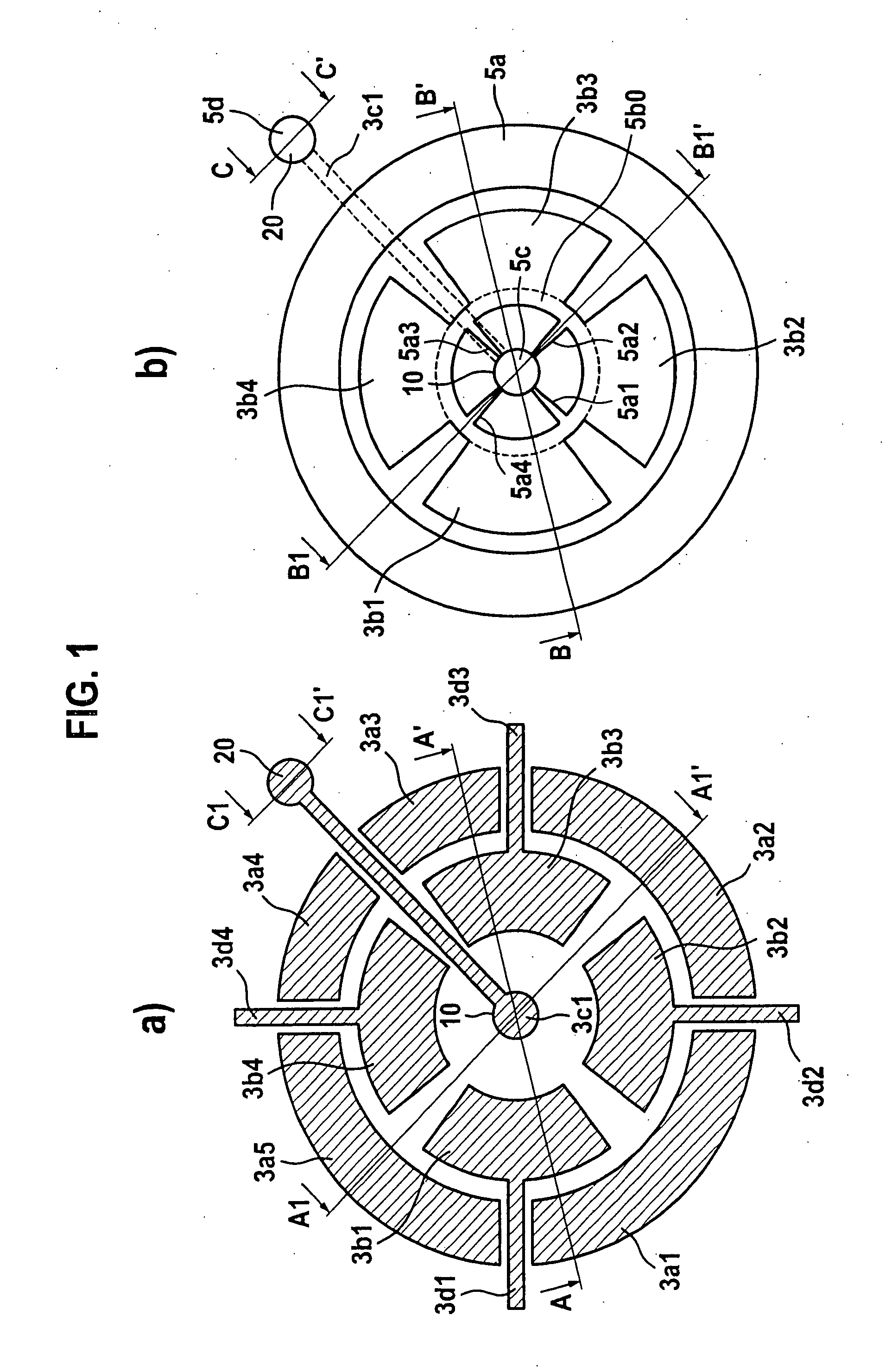
[0058] In the third embodiment according to FIG. 7, corrugation of upper deflectable electrodes 5b1, 5b2, 5b3, 5b4 is provided, in the present case as a design in the shape of an undulating elevation W. Also possible is a corrugation of bending springs 5a1, 5a2, 5a3, 5a4 for the relaxation of stress gradients and in-plane stress, a corrugation composed of a superimposition of concentric radial undulations and azimuthal undulations having proven to be particularly suitable. Various mechanical and fluid dynamic characteristics may be imparted by varying the perforation or corrugation of the bending beam segments.
[0059]FIG. 8 shows a sectional schematic top view of a micromechanical component according to a fourth example embodiment of the present invention.
fourth embodiment
[0060] In the fourth embodiment according to FIG. 8, a comb structure having teeth 52 and indentations 53 is also provided on circumferential third electrical electrode system 5a′, the comb structure being interlocked, i.e., engaged, with a corresponding comb structure, having teeth 50 and indentations 51, provided on electrodes 5b1′, etc. for the upper electrode system.
[0061]FIG. 9 illustrates a schematic top view of a micromechanical component according to a fifth embodiment of the present invention, and FIGS. 10 and 11 show sectional vertical cross-sectional views of the micromechanical component according to the fifth embodiment of the present invention, specifically, along line B2-B2′ and line B3-B3′ in FIG. 12, and FIG. 12 shows a schematic horizontal cross-sectional view of a micromechanical component according to the fifth embodiment of the present invention, through the movable electrode region.
PUM
 Abstract
Description
Claims
Application Information
 - R&D
- Intellectual Property
- Life Sciences
- Materials
- Tech Scout
- Unparalleled Data Quality
- Higher Quality Content
- 60% Fewer Hallucinations
Browse by: Latest US Patents, China's latest patents, Technical Efficacy Thesaurus, Application Domain, Technology Topic, Popular Technical Reports.
© 2025 PatSnap. All rights reserved.Legal|Privacy policy|Modern Slavery Act Transparency Statement|Sitemap|About US| Contact US: help@patsnap.com


