Information Recording Medium, Information Recording Device and Method, and Record Controlling Computer Program

Inactive Publication Date: 2007-09-20
PIONEER CORP
View PDF4 Cites 4 Cited by
  • Summary
  • Abstract
  • Description
  • Claims
  • Application Information

AI Technical Summary

Benefits of technology

[0011] More specifically, particularly, the first recording track may be directed from one to the other side, out of the inner circumferential side and the outer circumferential side of the above-described substrate. The second recording track may be directed from the one to the other side, as with the first recording track. Namely, on the two-layer type or multiple-layer type information recording medium, it is possible to perform continuous recording in a “parallel manner” in which the recording tracks are directed in the same direction between the two recording layers. In the “parallel manner”, if the recording or reproduction is ended in the first recording layer, an optical pickup that is on the most outer circumference of the optical disc needs to be displaced again to the most inner circumference when the recording or reproduction is started in the second recording layer. Thus, as compared to an “opposite manner”, it takes more time by that much to change from the L0 layer to the L1 layer. Alternatively, the first recording track may be directed from one to the other side, out of the inner circumferential side and the outer circumferential side of the above-described substrate. As opposed to this, the second recording track may be directed from the other to the one side. Namely, on the two-layer type or multiple-layer type information recording medium, it is possible to perform continuous recording in the “opposite manner” in which the recording tracks are directed in the opposite directions between the two recording layers. Therefore, if the recording is continuously performed from the end edge of the first recording layer, i.e. an edge on the other side of the first recording layer, such as an outer circumferential end portion of the first recording layer, to the start edge of the second recording layer, i.e. an edge on the other side of the second recording layer, such as an outer circumferential end portion of the second recording layer, it is hardly necessary or not necessary at all to change the irradiation position of the laser light in the substrate surface, in the radial direction, in changing the recording layers which is the object of recording processing or reproduction processing associated with the information. This allows the quick layer-to-layer jump (i.e. a layer-to-layer changing operation). This does not need a special buffer function to change the recording layers, in recording the continuous record information, such as a movie, for example. Moreover, this facilitates the reproduction without a stop, so that it is extremely useful in practice.
[0073] According to the second computer program of the present invention, the above-described second information recording apparatus of the present invention can be relatively easily realized as a computer reads and executes the second computer program from a program storage device, such as a ROM, a CD-ROM, a DVD-ROM, and a hard disk, or as it executes the second computer program after downloading the program through a communication device.

Problems solved by technology

Thus, there is a possibility that an error in pasting may cause an eccentricity in the L0 layer and the L1 layer.
Alternatively, since the L0 layer and the L1 layer are formed by using different stampas, that may cause deviation in a track pitch in each of the recording layers.
Thus, there is such a technical problem that the laser light is not always emitted to the another recording area of the L1 layer, through the one recording area, which is in the recorded condition, of the L0 layer.

Method used


Image

  • Information Recording Medium, Information Recording Device and Method, and Record Controlling Computer Program
  • Information Recording Medium, Information Recording Device and Method, and Record Controlling Computer Program
  • Information Recording Medium, Information Recording Device and Method, and Record Controlling Computer Program

Examples


Embodiment Construction

[0102] Hereinafter, the best mode for carrying out the invention will be explained in each embodiment in order, with reference to the drawings.

[0103] (Embodiment of Information Recording Medium)

[0104] Next, with reference to FIG. 1 to FIG. 3, an embodiment of the information recording medium of the present invention will be explained in detail.

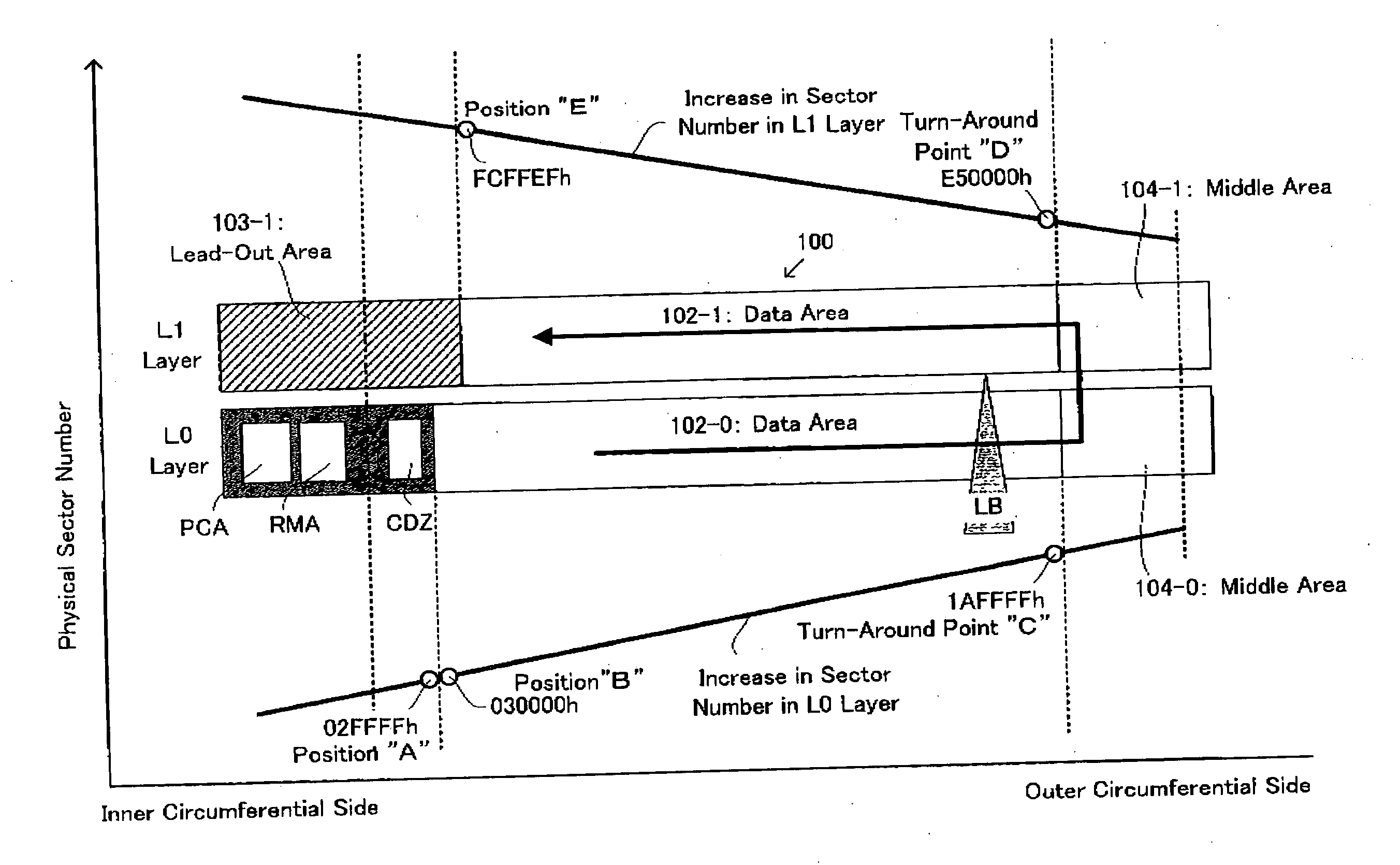
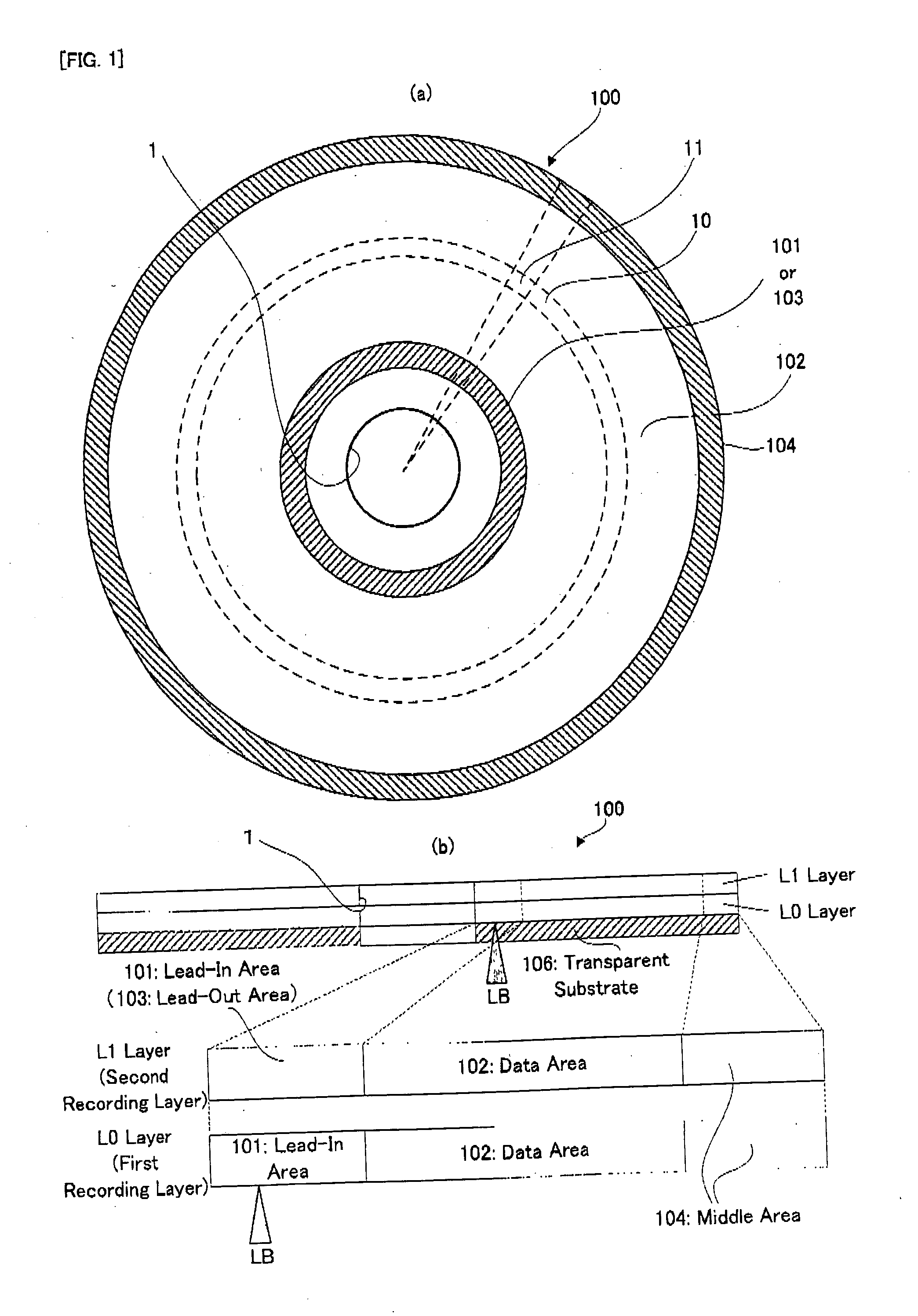
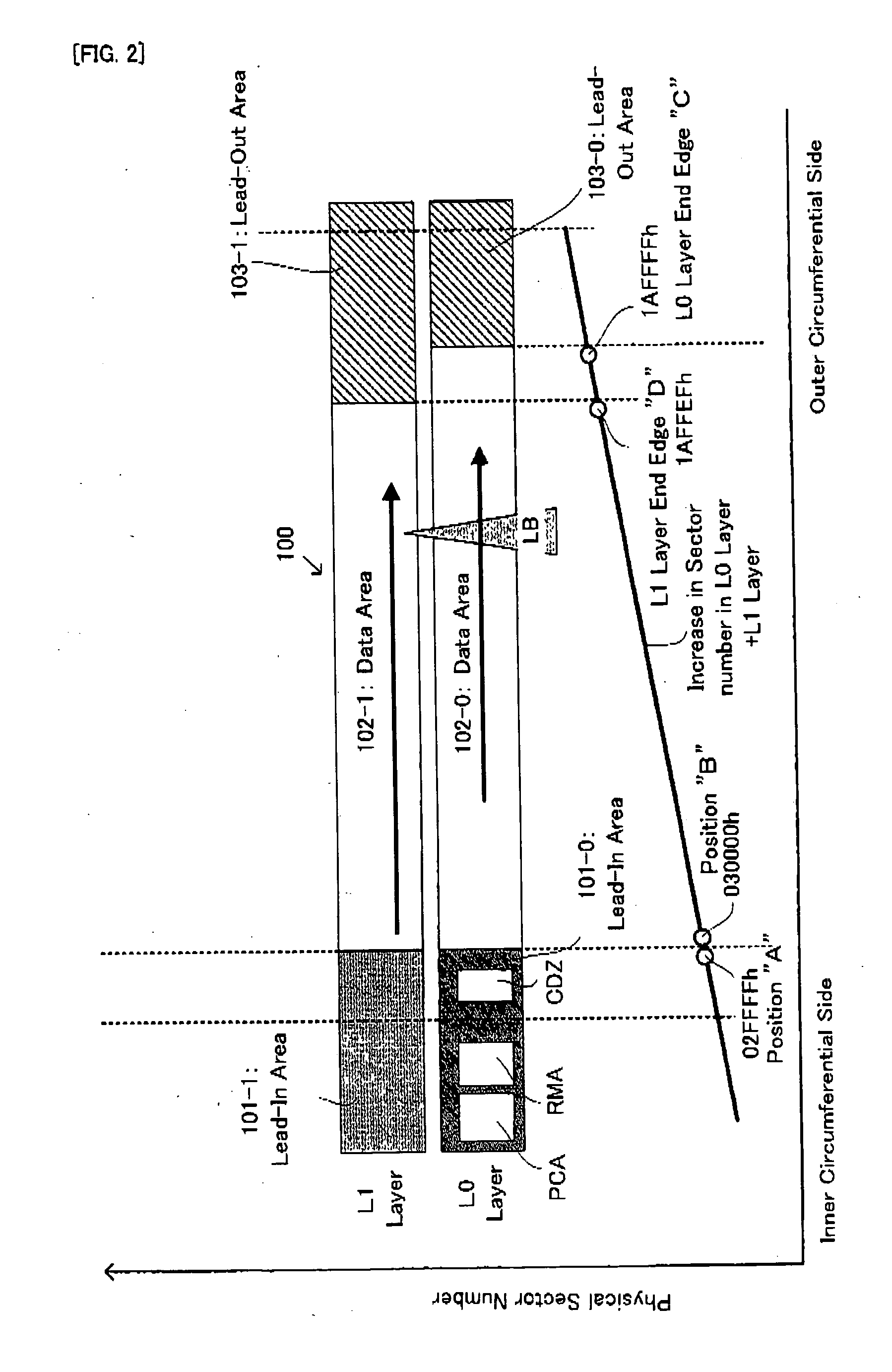
[0105] Firstly, the basic structure of an optical disc in the embodiment of the information recording medium of the present invention will be explained with reference to FIG. 1(a) and FIG. 1(b). FIG. 1(a) is a substantial plan view showing the basic structure of an optical disc having a plurality of recording areas in the embodiment of the information recording medium of the present invention, and FIG. 1(b) is a schematic cross sectional view of the optical disc and a corresponding conceptual diagram showing a recording area structure in the radial direction.

[0106] As shown in FIG. 1(a) and FIG. 1(b), an optical disc 100 has a recording su...


PUM


Abstract

An information recording device is provided with a writing device for writing recording information in a first recording layer and a second recording layer of an information recording medium; an acquiring element for acquiring information relating to an offset quantity; and a calculating member for calculating a start position where the recording information can be recorded in the second recording layer, based on the acquired information. The information recording device is also provided with a control unit which controls the writing device to i) write the recording information in the first recording layer along a first recording track, and ii) write the recording information in the second recording layer along a second recording track from the calculated start position.

Description

TECHNICAL FIELD [0001] The present invention relates to an information recording medium, such as a DVD and a Compact Disc (CD), an apparatus for and a method of recording information onto such an information recording medium, and a computer program for record control. BACKGROUND ART [0002] For example, with respect to an information recording medium, such as a Compact Disc-Read Only Memory (CD-ROM), a Compact Disc-Recordable (CD-R), a DVD-ROM, a DVD-R, a DVD-R / W, and a DVD+R, an information recording medium, such as an optical disc, of a multi-layer type or of a dual-layer-type in which a plurality of recording layers are laminated or pasted on the same substrate has also been developed, as described in patent documents 1 and 2 and the like. Moreover, on an information recording apparatus, such as a DVD recorder, which records information onto such a dual-layer type optical disc, i.e. a two-layer type optical disc, laser light for recording is focused on a recording layer which is o...

Claims


Application Information

Patent Timeline
IPC IPC(8): G11B7/0045G11B7/007G11B7/24038G11B20/10G11B20/12
CPCG11B7/00736G11B7/24038G11B20/10G11B20/1217G11B2220/2562G11B2020/1268G11B2020/1292G11B2020/1298G11B2220/235G11B2020/1227
Inventor KATATA, KEIJINAMIKI, TSUYOSHIKODA, TAKESHIKATO, MASAHIRO
Owner PIONEER CORP
Why Eureka
Try Eureka