Unfortunately, at times, and especially at lower resolutions, the results of
scan conversion produce an unacceptable representation of a character.
Unacceptable character representations can result from
rounding errors in the scaling down process or from the
scan conversion process itself.
Further,
rounding errors have a greater affect on character representation when a single grid location (e.g., a pixel) is on scale with the features of a character.
For example, a rounding error that causes one grid location to be inappropriately turned on (or turned off) on a 50×50 grid may not even be detectable by the
human eye.
However, a rounding error that causes one grid location to be inappropriately turned on (or turned off) on a 4×4 grid may result in a character that is perceived as unacceptable to the
human eye.
Thus, at lower resolutions
scan conversion can even fail to preserve the topology of the original outline of the character, for example, causing disconnected grid locations, inappropriately located features, and lack of symmetry.
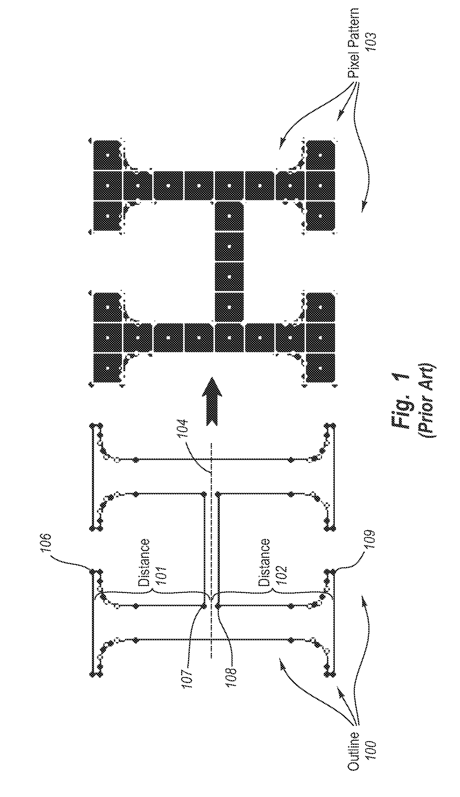
However, by the time the “H” is rendered at a smaller size and lower resolution (e.g., 9 pt on a 96 dpi device), accumulated quantization errors can result in the cross-bar being rendered below the mathematical halfway point.
One cause of non-optimal rendering results from the “H” having control points on the edges of the cross-bar, but not having control points, for example, on an imaginary line (represented by dashed line 104) along the center between the edges of the cross-bar.
In unfortunate cases, these rounding errors accumulate (e.g., both the first and second constraints round down)—to place the cross-bar below the mathematical halfway point.
Italic fonts
pose a particularly challenging problem because the jagged nature of
diagonal strokes makes italic fonts more difficult to process, and quantization errors can compound the problem.
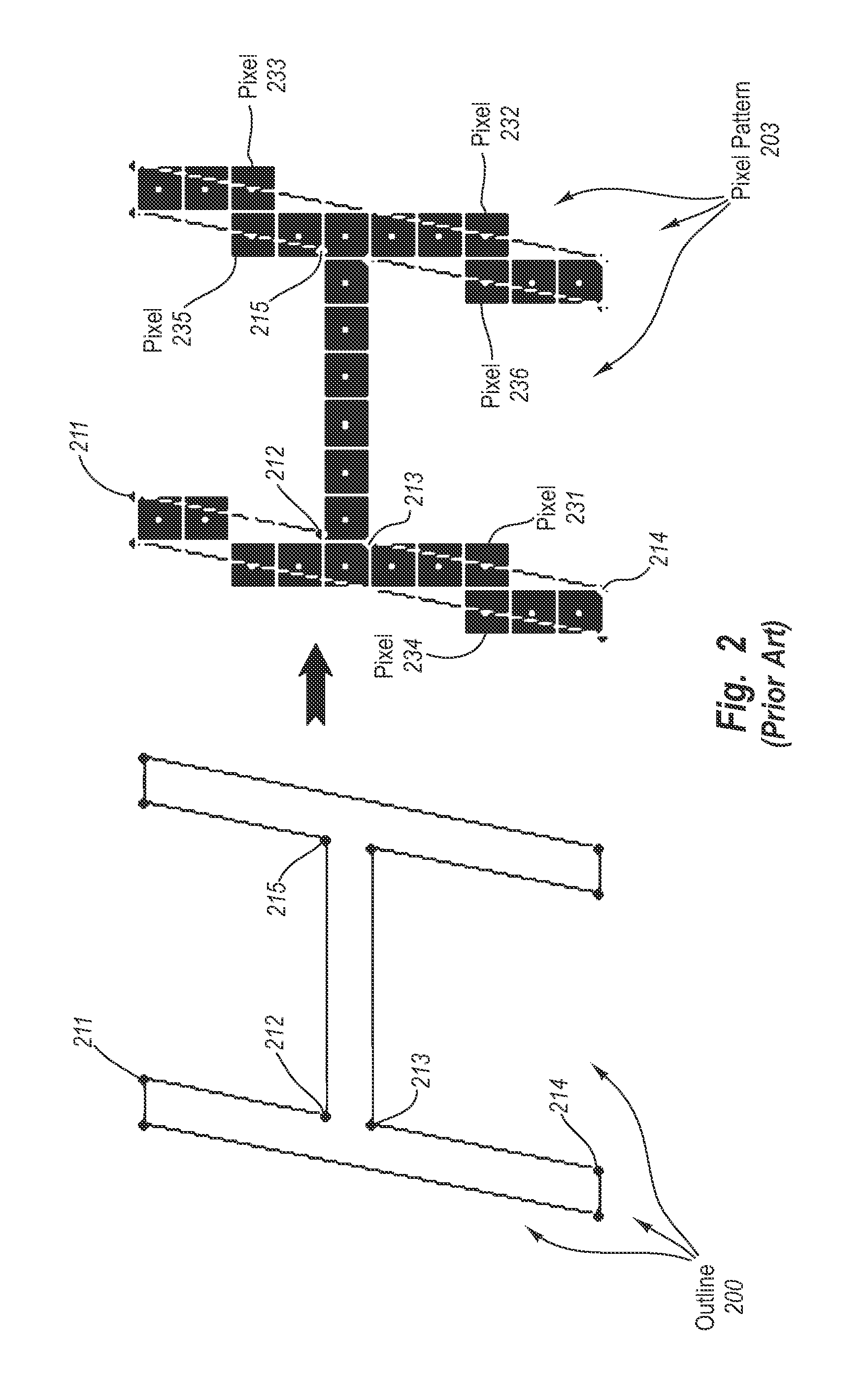
Further, even when pixels having their centers exactly on an outline are turned off problems can still occur.
While this could solve the problem for some italic strokes, such an alternating approach would also introduce new problems on round strokes.
Further, any movement of control points to comply with constraints can cause control points to be moved to inexact locations.
Utilizing a
control point that is at an inexact location for further calculations can result in non-optimal rendering of a corresponding character in a grid space.
While the act of aligning is a mathematically exact concept, its implementation in terms of a
font hinting language (e.g., TrueType®) likely introduces numerical inaccuracies, because the internal
numerical precision of
font hint processors is typically limited.
Unfortunately, 12.8 / 64 is beyond the precision limit of most, if not all,
font hint processors.
Thus, even if rounding were to be correct, alignment problems can still result.
Additionally, character outlines that have too many control points can result in non-optimal rendering of a corresponding character in a grid space.
For example, erroneous pixels can potentially arise when the exact shapes of outlines have increased complexity.
Unfortunately, some hint processors refer to control points by consecutive number and removing a
control point can cause other control points to be renumbered.
Thus, renumbering control points can cause existing hinting instructions to refer to incorrect
control point numbers.
For example, removing what may be viewed as extraneous control points on outline 300 could cause existing hints to be inappropriately applied to any remaining control points (or not be applied at all).
That is, for each type size (of a font) at which there is an unfortunate quantization problem, the human typographer has to add possibly a plurality of
delta-exception instructions, as appropriate.
Moreover, the use of
delta-exception hints is an iterative process requiring repeated
visual inspection of a plurality of type sizes before and after the application of corresponding exception instructions, which is laborious and prone to introduction of inconsistencies.
That is,
delta-exception hints for one font typically can not be reused for other fonts (even for the same character).
Further difficulties can occur for characters that have more than one stroke feature.
The combined positioning results in accumulated rounding error with respect to character width or stroke-to-stroke distance.
However, by the time the “H” is rendered at a smaller size and lower resolution (e.g., 9 pt on a 96 dpi device), accumulated quantization errors, can result in non-optimal, or even inappropriate, rendering of the Times New Roman capital “H”.
Although default behavior may be used to cause two strokes to be rounded in the same direction, this can also result in consecutive glyphs becoming indistinguishable due reduced space between the glyphs.
