
Method and Apparatus for Dispensing Liquid with Precise Control

a technology of precise control and liquid, applied in the direction of fluid pressure control, process and machine control, instruments, etc., can solve the problems of loss of yield, affecting the pressure in the distribution system, and changes in flow rate, so as to optimize the advantages of each component and enhance the overall performance of the system

Inactive Publication Date: 2007-09-20
AIR LIQUIDE ELECTRONICS US LP
View PDF15 Cites 10 Cited by
  • Summary
  • Abstract
  • Description
  • Claims
  • Application Information

AI Technical Summary

Benefits of technology

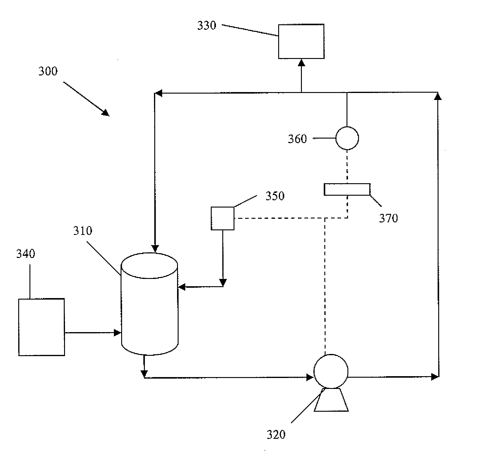
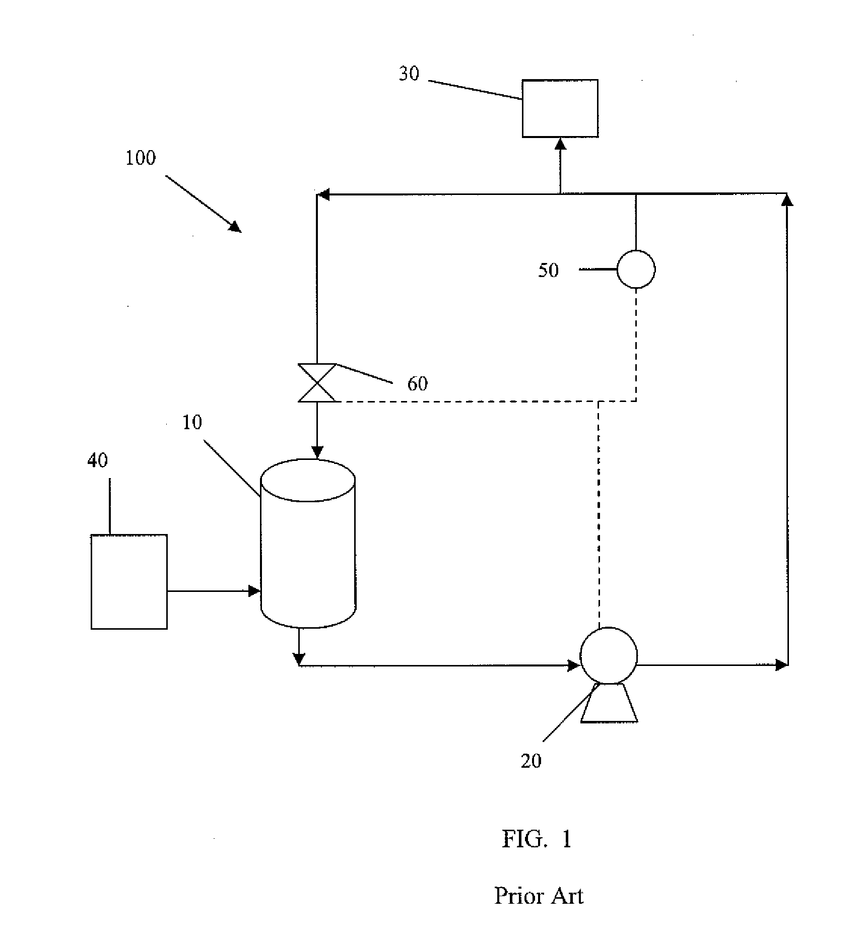
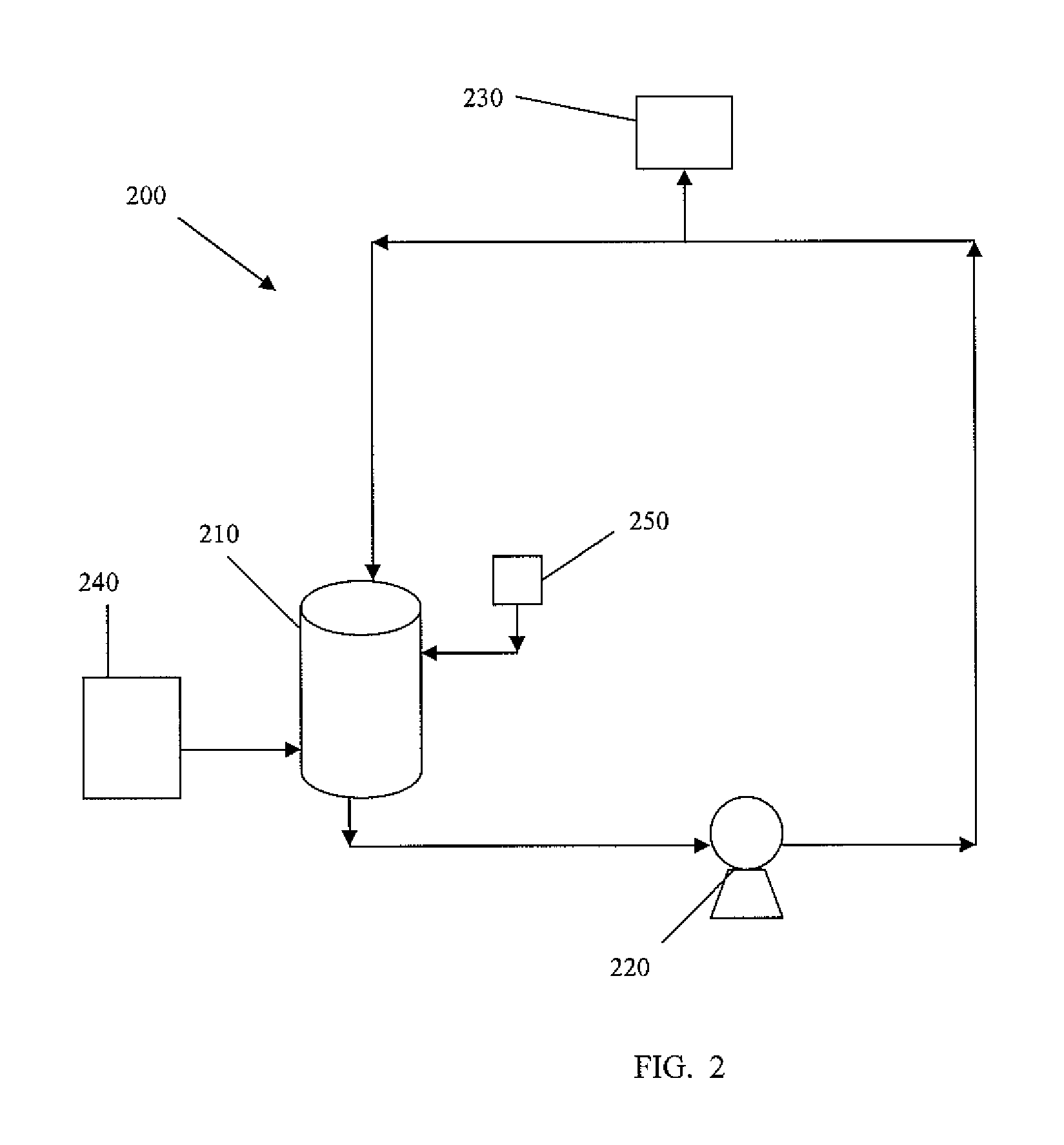
[0010] The objectives of the present invention are accomplished by combining a pressure vessel and a centrifugal pump within the same distribution system. By using both a pressure vessel and a centrifugal pump together, the advantages provided by each component can be optimized and the overall performance of the system can be enhanced.

Problems solved by technology

Variations in pressure can lead to non-repeatability and ultimately a loss in yield.
Changes in flow rate can also affect the pressure in the distribution system, such as by frictional losses (e.g. headloss) in piping or filtration cartridges.
However, this can be difficult to achieve for a number of reasons, including, variations in demand, pressure changes in the distribution system during operation, pressure changes caused by filter clogging, pump cycle effects, and others.
However, large consumption demands or disruptions in the distribution system, e.g. charging an empty filter housing, can cause flow transients that significantly reduce the output pressure of the centrifugal pump and therefore significantly effect the pressure in the distribution system.
Further, centrifugal pumps demand a high amount of electrical power and have limitations on discharge pressure.
Reaching higher pressures requires more electrical power and centrifugal pumps running at the high RPMs needed for high pressure operation, can introduce heat into the system that may negatively impact some processes.
However, as will also be recognized, additional points of use add to the complexity of the system and make it harder to maintain system pressure and flow rate.
These components also add complexity to the system.
For example, multiple pressure vessels that operate in sequence can provide the most stable pressure for the system, but suffer from system complexity because of the need to continually pressurize, empty, vent and refill as liquid is circulated through the system.
When liquid demand is low, significant energy is still consumed because of the necessity of maintaining the re-circulating flow.

Method used


Image

  • Method and Apparatus for Dispensing Liquid with Precise Control
  • Method and Apparatus for Dispensing Liquid with Precise Control
  • Method and Apparatus for Dispensing Liquid with Precise Control

Examples


Embodiment Construction

[0015] The present invention now will be described more fully hereinafter with reference to the accompanying drawings, in which preferred embodiments of the invention are shown. This invention may, however, be embodied in many different forms and should not be construed as limited to the embodiments set forth herein. Rather, these embodiments are provided so that this disclosure will be thorough and complete, and will fully convey the scope of the invention to those skilled in the art.

[0016]FIG. 2 is a schematic view of a basic system according to one embodiment of the present invention. In particular, FIG. 2 shows a liquid distribution system 200, comprising a pressure vessel 210 that can be refilled from a liquid source 240, a centrifugal pump 220, and a point of use 230. While only a single point of use 230 is shown, it will be recognized by those skilled in the art, that multiple points of use may be supplied with liquid using the same distribution system 200. Also shown is a p...


PUM


Abstract

The present invention provides methods and apparatus combining a pressure vessel and a centrifugal pump to accurately and efficiently control pressure and flow rate of liquid in a liquid dispense system. The present invention particularly relates to the accurate and efficient control of pressure and flow rate of liquids, such as high purity chemicals or slurries used in semiconductor manufacturing processes.

Description

FIELD OF THE INVENTION [0001] The present application provides methods and apparatus for the delivery of liquids under conditions that require highly accurate control of pressure or flow rate. In particular, the present invention provides methods and apparatus for the delivery of high purity chemicals or slurries to one or more points of use in a semiconductor manufacturing process, wherein the flow rate of the chemical or slurry is provided at a constant flow rate to the points of use. BACKGROUND OF THE INVENTION [0002] It is often desirable to precisely control the amount of liquid provided to an end point of a liquid dispensing system. Further, it is important that the amount of liquid provided is as constant as possible to avoid spiking that can have deleterious effects. This is particularly true for semiconductor manufacturing processes where the amount of liquid provided can greatly affect the process, such as layer formation, etching, cleaning, etc. Variations in pressure can...

Claims


Application Information

Patent Timeline
Patent Type & Authority Applications(United States)
IPC IPC(8): B67D5/08B65D88/54B67D7/08
CPCB67D7/0238G05D16/2006
Inventor ROBERTS, BENJAMIN R.GERKEN, DAVID ALANSMITH, BRYAN LANE
Owner AIR LIQUIDE ELECTRONICS US LP
Learn More