
System for spatial backoff contention resolution for wireless networks

a wireless network and backoff contention technology, applied in the field of data transmission in wireless networks, can solve the problems of poor link quality, inability to fully explore spatial reuse, and inability to achieve the benefits of “spatial backoff” and other problems, to achieve the effect of reducing the overhead of resolving “local” channel contention, reducing channel bit rate, and reducing the number of competing stations

Inactive Publication Date: 2007-09-13
THE BOARD OF TRUSTEES OF THE UNIV OF ILLINOIS
View PDF2 Cites 39 Cited by
  • Summary
  • Abstract
  • Description
  • Claims
  • Application Information

AI Technical Summary

Benefits of technology

The patent text describes a method for improving network performance by adjusting the carrier sense threshold and transmission rate control. By doing so, the contending area can be adjusted to allow more concurrent transmissions, reducing the MAC overhead and increasing the aggregate throughput. The method also allows for dynamic adjustment based on transmission success or failures, leading to improved performance. Overall, the method allows for better utilization of network resources and improved overall performance.

Problems solved by technology

The patent text discusses a method for improving network throughput by adjusting the way stations access the network's channels. The problem is that existing methods only adjust transmission rate or carrier sense threshold, but not both at the same time. The proposed method allows for better spatial reuse, meaning more concurrent transmissions can occur, leading to increased throughput.

Method used


Image

  • System for spatial backoff contention resolution for wireless networks
  • System for spatial backoff contention resolution for wireless networks
  • System for spatial backoff contention resolution for wireless networks

Examples


Embodiment Construction

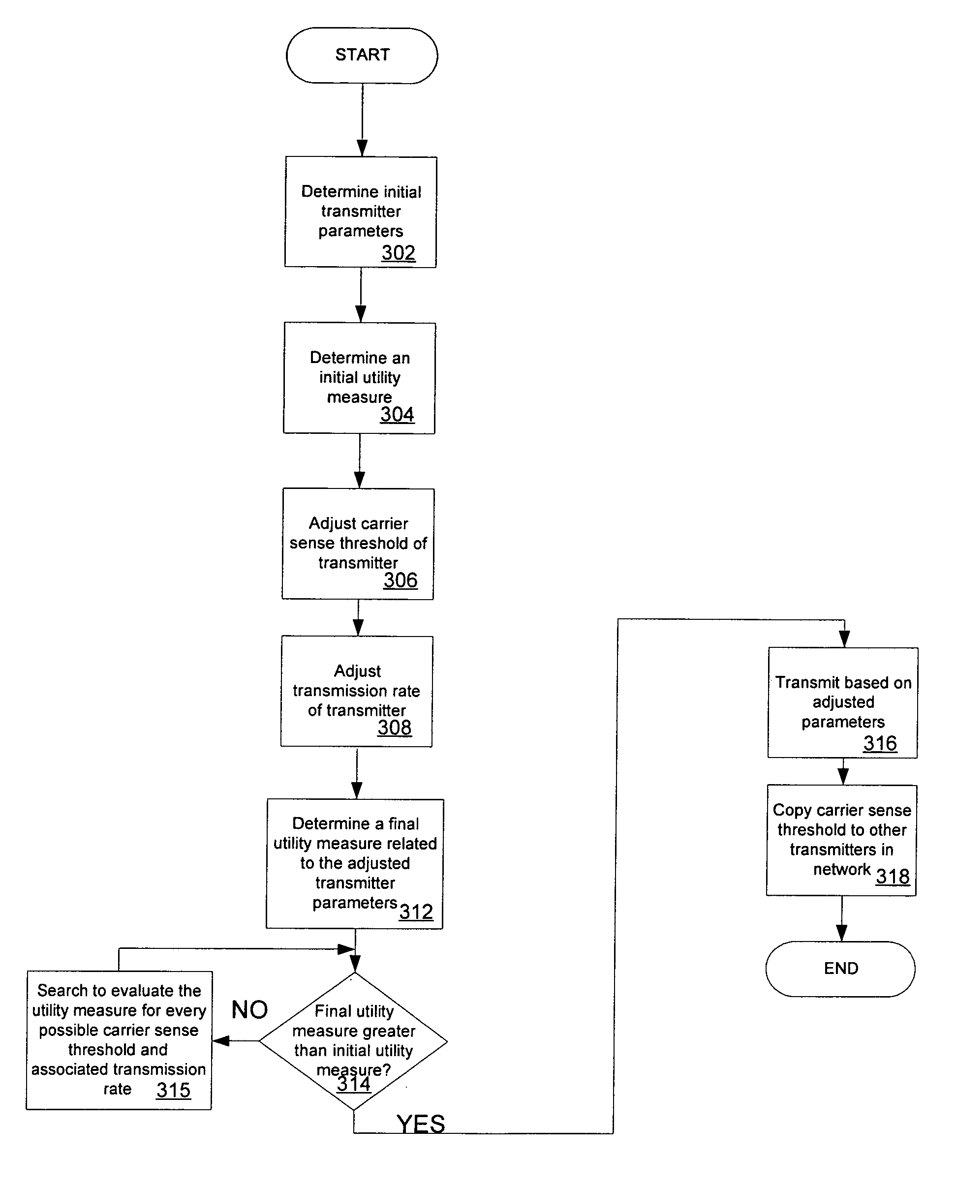
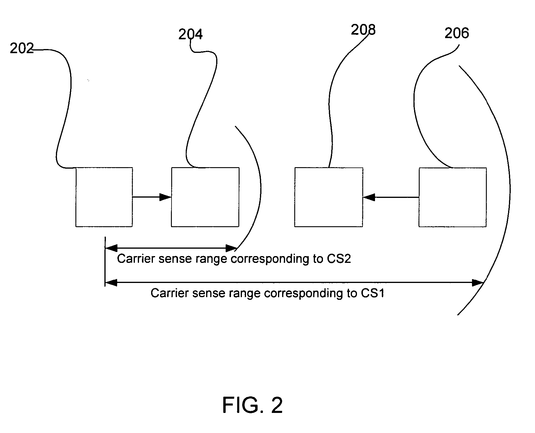
[0024] Spatial backoff methods allow source stations to search for appropriate carrier sense threshold and transmission rate operating points to improve network aggregate throughput. For a given a carrier sense threshold CSth, the corresponding Carrier Sense Range D may be defined as the minimum distance allowed between two concurrent transmitters. A larger carrier sense threshold may lead to a smaller carrier sense range.

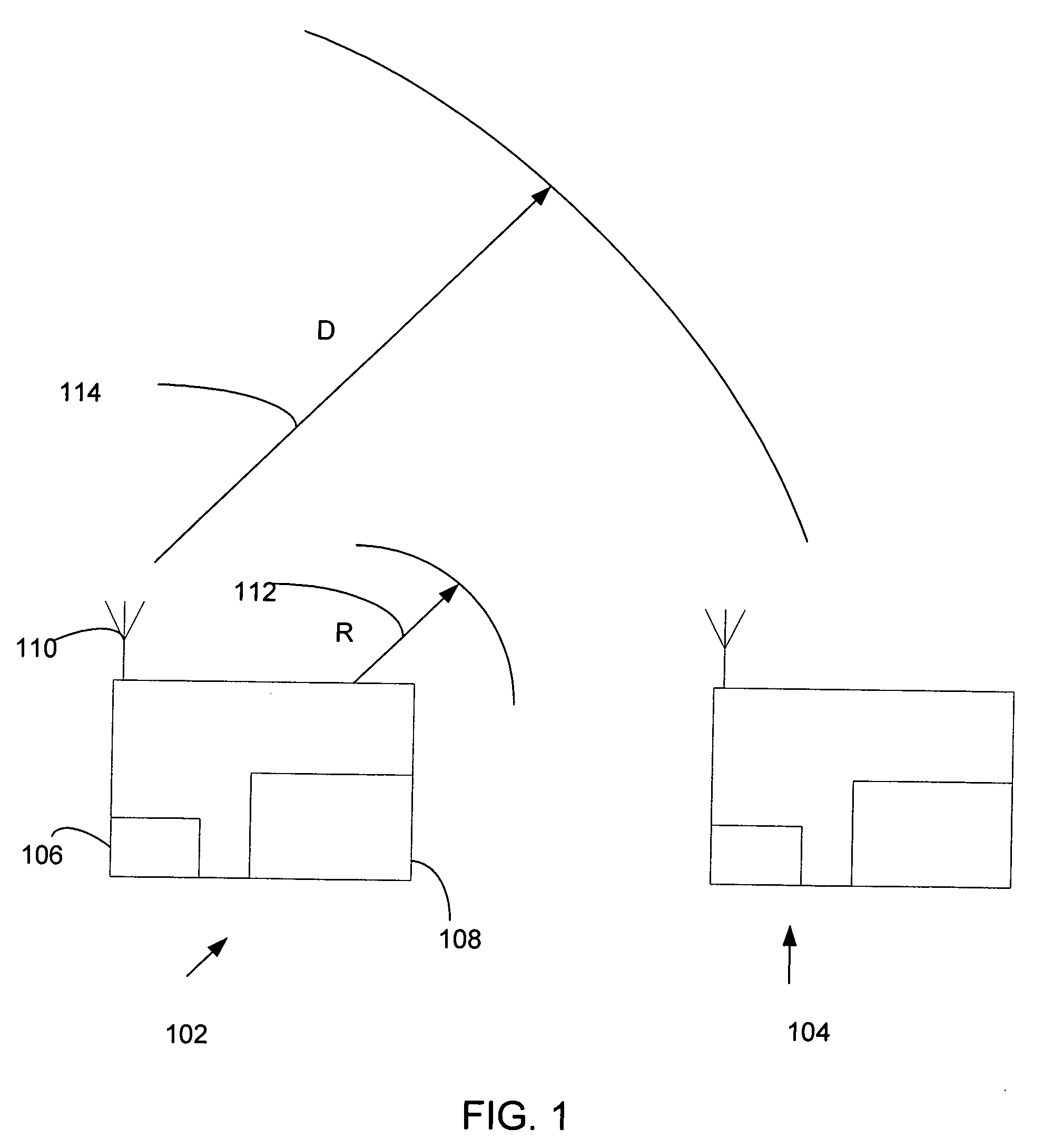
[0025]FIG. 1 illustrates a wireless network system 100. The network system 100 may include one or more transmitter stations, such as transmitters 102 and 104. The transmitters 102 and 104 may include receivers 106, secondary radio modules 108, and transmitting antennae 110. The transmitters 102 and 104 may be in a dense network system, where the transmitters 102 and 104 are located close to one another relative to their transmission ranges. The transmitters 102 and 104 may be uniformly and independently distributed in an area of A. A common and fixed transmission ...


PUM


Abstract

Spatial backoff methods allow source stations to search for appropriate carrier sense threshold and transmission rate operating points to improve network aggregate throughput. In one method, each source station performs a search process to find the best carrier sense threshold and transmission rate, based on a defined utility function. In a second method, each source station dynamically adjusts its carrier sense threshold and transmission rate upon successful transmissions or failures, based on some heuristic measures. Spatial backoff methods may lead to gains in performance.

Description


Claims


Application Information

Patent Timeline
Owner THE BOARD OF TRUSTEES OF THE UNIV OF ILLINOIS
Learn More