
Contact pin and method for the production thereof

Inactive Publication Date: 2007-09-13
KRAMSKI
View PDF0 Cites 26 Cited by
  • Summary
  • Abstract
  • Description
  • Claims
  • Application Information

AI Technical Summary

Benefits of technology

[0020]Proceeding from this prior art, the present invention is based on the object of providing a contact pin and a method for the production thereof, which can be produced by punching in conformity with standards, with optimum extraction forces.
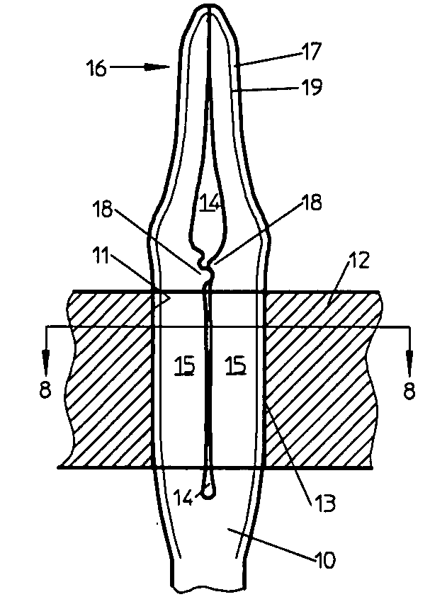
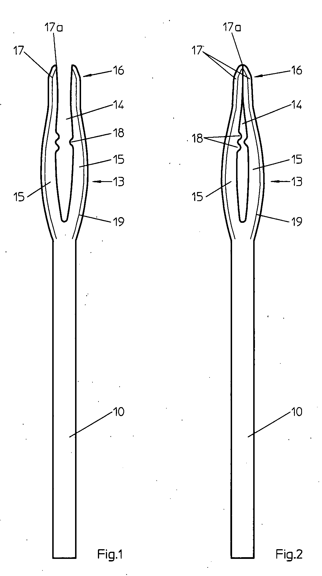
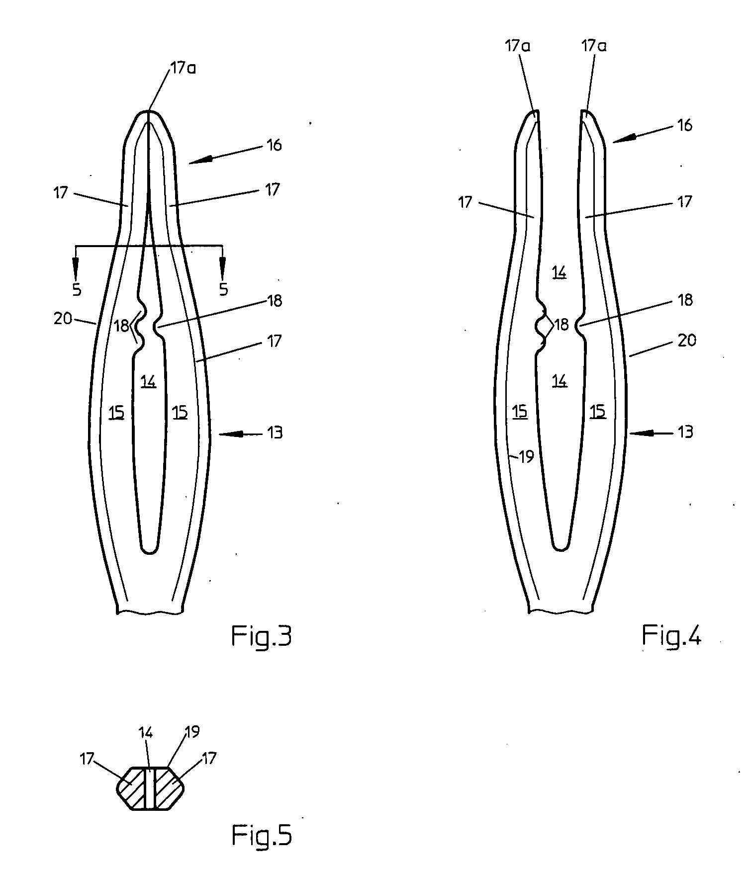
[0022]The contact pin has an open shape, in which, after the punching process, the elongate opening forming the later slot is open to the outside and lies between the portions, which later form the introduction portion of the contact pin. With the therefore initially open, fork prong-like shape of these portions, which then rest on one another during introduction into the hole, the limitations of the punching technology can be avoided. At the same time, each basic shape of a contact pin can be produced so as to be larger or smaller without problems, i.e. the press-in and press-out forces can be better defined and are softer or harder, for example, in the transition regions, which is not possible in current punching technology with a closed needle eye. Any geometric formations are formed inside the elongate opening to thus form support regions, for example. These support regions can control the elastic-plastic behavior by means of the different hole diameters. In addition, the formations may preferably come to rest in the hole itself. However, they can also lead to a type of tilting movement, which allows the region overlaid by the hole to become wider than the press-in region, which leads to increased press-out forces. Good clamping forces can consequently still be produced even with a reducing sheet thickness and a smaller hole diameter. Tests have shown that even with small bore diameters of 1.0 mm and sheet thicknesses of 0.6 mm a reliable connection can still be produced.

Problems solved by technology

However, they can also lead to a type of tilting movement, which allows the region overlaid by the hole to become wider than the press-in region, which leads to increased press-out forces.

Method used


Image

  • Contact pin and method for the production thereof
  • Contact pin and method for the production thereof
  • Contact pin and method for the production thereof

Examples


Embodiment Construction

[0036]The invention will now be described in more detail by way of example with reference to the accompanying drawings. However, the embodiments are only examples, which are not intended to restrict the inventive concept to a specific arrangement. Before the invention is described in detail, reference is made to the fact that it is not limited to the respective components of the device or the described procedure, as these components and methods may vary. The terms used here are only intended to describe special embodiments and are not used in a restrictive manner. If, in the description and in the claims, the singular or indefinite article is used, these also refer to the plurality of these elements, as long as the overall context does not unambiguously make clear something else. The same applies in the reverse direction.

[0037]The Figures show a contact pin 10 from a formed material for pressing into a through-connected hole 11 on a printed circuit board 12, which is shown in FIG. 7...


PUM


Abstract

A contact pin for pressing into a through-connected hole of a printed circuit board is produced by forming. Its press-in portion has two contact legs spaced apart from one another by an elongate opening, are outwardly curved in their central region and, when pressed into the circuit board come to rest with plastic deformation on the wall of the hole. A portion for introduction into the hole includes at least two elongate portions resting on one another during introduction. These portions, after forming and before introduction into the hole adjoin the outwardly open elongate opening like fork prongs. As a formation projects into the opening at an edge thereof to form support regions which, after introduction of the contact pin into the hole, are located inside the hole, a contact pin and a method for the production thereof are provided, by punching in conformity with standards, with optimum extraction forces.

Description

REFERENCE TO RELATED APPLICATIONS[0001]The present application claims the priority of the German patent application 10 2006 011 657.7, filed on 12 Mar. 2006, the disclosure content of which is expressly also made the subject of the present application.FIELD OF THE INVENTION[0002]The invention relates to a contact pin with a contact region and a connection region for pressing into a through-connected hole of a printed circuit board according to the preamble of claim 1 and a method for the production thereof according to the preamble of claim 12.PRIOR ART[0003]Contact pins of this type are provided, in particular, for producing a solder-free, electrically conductive connection to at least one conductor track of the printed circuit board by pressing into metalized punchings of electric printed circuit boards. For perfect contacting of the punching, the manufacturing tolerances thereof have to be compensated by corresponding configurations of the press-in portion of the contact pin, so ...

Claims


Application Information

Patent Timeline
IPC IPC(8): H01R12/00H01R12/55H01R12/58
CPCH01R43/16H01R12/585
Inventor KRAMSKI, WIESTAW
Owner KRAMSKI
Learn More