
System and method for an Ethernet optical area network

a technology of optical area network and optical fiber, applied in the field of voice and data communication, can solve the problems of inconvenient use of transmission media most often used by the central switching office of local telephone companies, inability to achieve high-speed data transmission, and inability to meet the needs of high-speed data transmission, so as to improve the speed and reliability of data communication networks. , the effect of improving the speed and reliability of data communication

Inactive Publication Date: 2007-09-13
511 TECH
View PDF13 Cites 6 Cited by
  • Summary
  • Abstract
  • Description
  • Claims
  • Application Information

AI Technical Summary

Benefits of technology

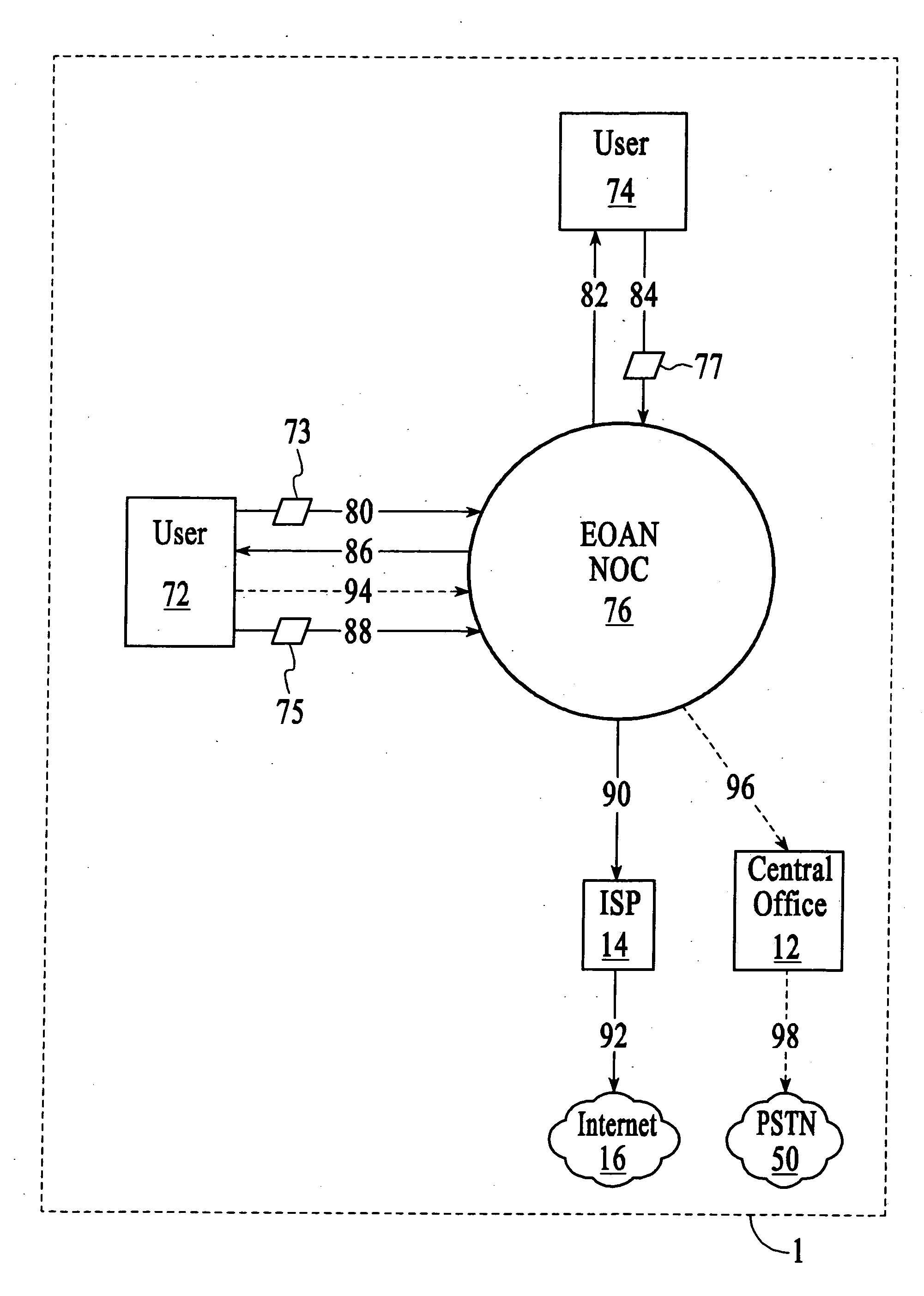
[0009] The present invention provides what is referred to herein as Ethernet Optical Area Network (EOAN) system, and methods for implementing and using such an EOAN system. In accordance with the present invention, an EOAN system is provided that may be used to improve the speed and reliability of data communications networks for small to medium-sized companies in metropolitan area networks. An EOAN system provides end-to-end Ethernet protocol, enabling professionals to have high-speed data communications in real time. As will be appreciated, the present invention may be generally utilized for improving data communications between branch offices, home offices, campuses, and remote sites for a wide variety of industries. The present invention preferably includes a fiber optic ring, Network Operation Center (NOC), NOC architecture components, existing client equipment, and one or more Free Space Optic (FSO) devices, microwave communication technology, and / or data switching platforms to implement high-speed Ethernet-based connections within a specified metropolitan area. The present invention preferably integrates a plurality of FSO, microwave, and / or fiber optic technologies with Ethernet protocol (Fast Ethernet, Gigabit Ethernet, 10 Gigabit, etc.) to provide data connection services that will enable users to connect at rates that may be potentially more than 80 times the current, conventional bandwidth connections.

Problems solved by technology

The public telephone system places inherent limits on the development of efficient, high-speed, digital data transmissions.
Thus, the transmission media most often used by the central switching offices of local telephone companies is not conducive to high-speed data transmission.
These companies have invested billions of dollars in building the “last mile” with UTP cable, but such technology now acts as a bottleneck to the transmission of large data files and streaming media between offices outside the LAN.
As applications grow more complex, the various types of files (data, graphic, audio, video, etc.) have tended to grow larger and larger.
For example, medical networks require high-speed data rates to achieve timely and efficient data communications between separate facilities, such as hospitals, clinics and research institutes, but UTP cable does not transmit well over anything but very short distances.
Currently, data from most medical equipment, such as a Magnetic Resonance Imaging (MRI) system, cannot be efficiently transmitted between separate facilities because the data files (which frequently include numerous images) are typically too large.
The problem is the present bandwidth of most medical intranets cannot achieve the necessary speeds for efficient data transmission between facilities outside of a LAN environment.
Remote hosting has also been restricted by the limitations of the public telephone network.
Such EOAN systems, for example, will allow businesses within the same metropolitan area to create private networks with unparalleled speed and ease of management at a fraction of the present cost.

Method used


Image

  • System and method for an Ethernet optical area network
  • System and method for an Ethernet optical area network
  • System and method for an Ethernet optical area network

Examples


Embodiment Construction

[0026] The present invention will now be described in greater detail with reference to particular preferred and alternative embodiments. Such description is for a more complete understanding of the background, utility and application of the present invention, and is without being bound by any particular theory or the like.

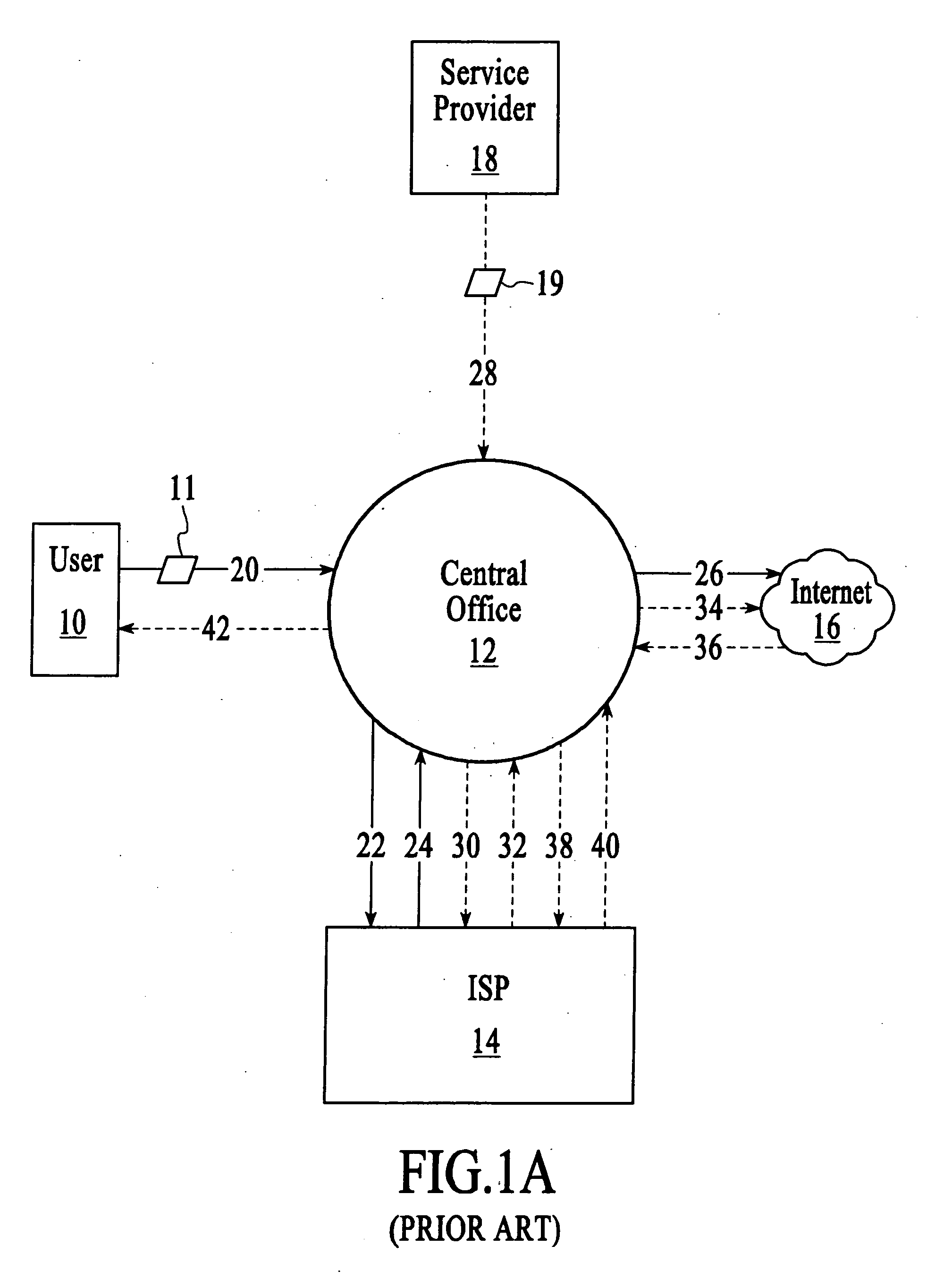
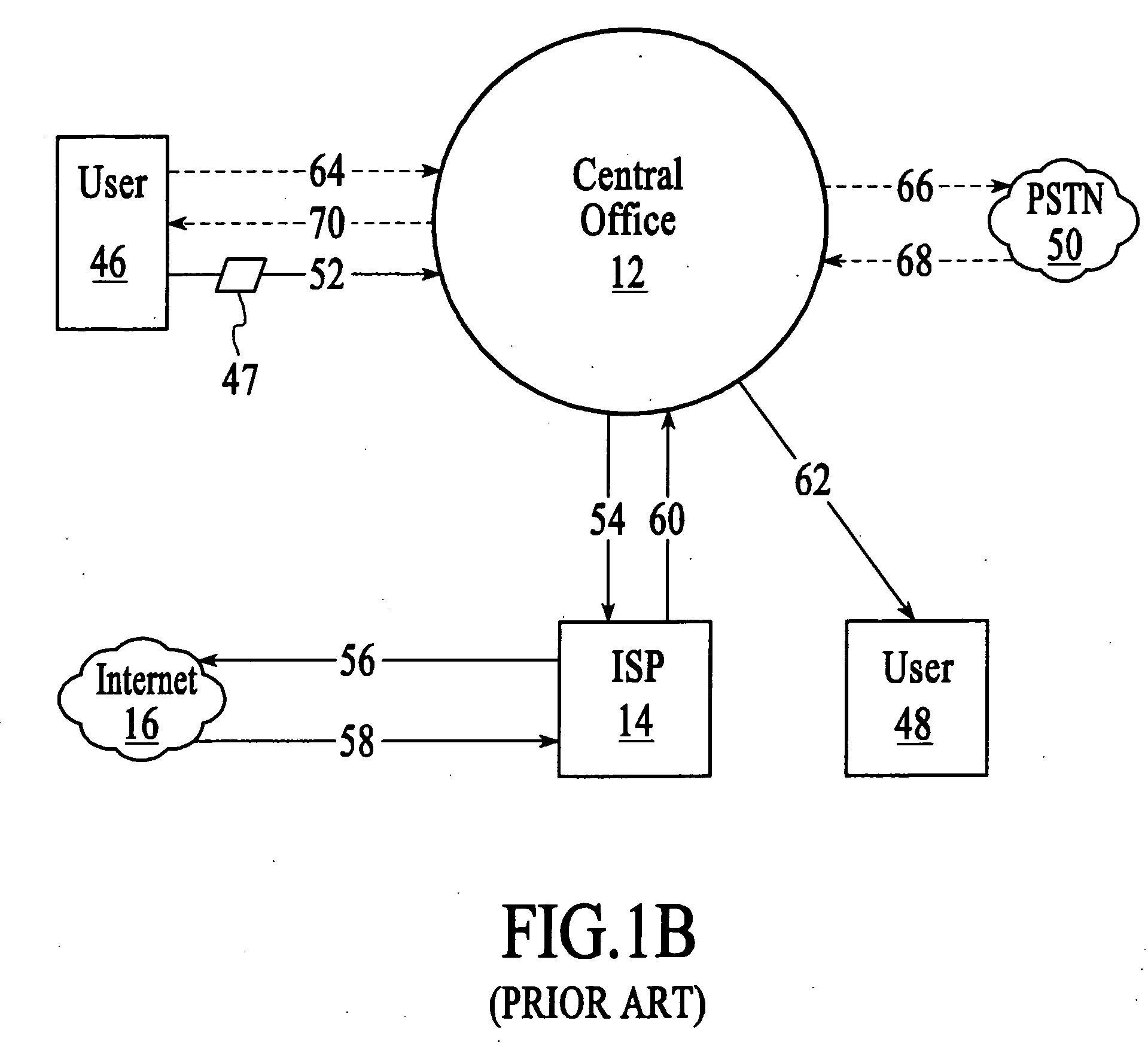
[0027]FIG. 1A is a diagram illustrating a conventional network topology for data communications using a central switching office of a local telephone company. In accordance with current conventions, user 10 is coupled to central office 12, which is connected to ISP 14, Internet 16, and service provider 18. Typically user 10 is a single location business without a Dedicated Access Line (DAL) such as a T-1 connection. Central office 12 is a central switching office of a local telephone company. ISP 14 is an Internet Service Provider that provides a variety of utilities and services to users (such as user 10, etc.) and is connected to one or more Network Access Point...


PUM


Abstract

An Ethernet Optical Area Network (EOAN) system, and methods for implementing and using such an EOAN system, are disclosed. The EOAN system may be used to improve the speed and reliability of data communications networks for small to medium-sized companies in metropolitan area networks. The EOAN system provides end-to-end Ethernet protocol, enabling professionals to have high-speed data communications in real time. The EOAN system may be generally utilized for improving data communications between branch offices, home offices, campuses, and remote sites for a wide variety of industries. The present invention preferably includes a fiber optic ring, Network Operation Center (NOC), NOC architecture components, existing client equipment, and one or more Free Space Optic (FSO) devices, microwave communication technology, and / or data switching platforms to implement high-speed Ethernet-based connections such as within a specified metropolitan area. The preferred EOAN system preferably integrates a plurality of FSO, microwave, and / or fiber optic technologies with Ethernet protocol (Fast Ethernet, Gigabit Ethernet, 10 Gigabit, etc.) to provide data connection services.

Description

FIELD OF THE INVENTION [0001] The invention generally relates to the fields of voice and data communications, specifically metropolitan area networks, Ethernet networks and fiber optic rings. More particularly, the present invention relates to an Ethernet optical area network system and methods for providing Ethernet protocol end-to-end and uses thereof. BACKGROUND OF THE INVENTION [0002] Data communications is one of the fastest growing segments of the telecommunications industry. Bandwidth, speed, latency, reliability, security, and Quality of Service (QoS) remain paramount concerns for data communications networks. However, current data communication networks connect to and often include the public telephone system, which was originally designed for analog (voice) communications. The public telephone system places inherent limits on the development of efficient, high-speed, digital data transmissions. [0003] Currently data routing through a central switching office occurs across ...

Claims


Application Information

Patent Timeline
Patent Type & Authority Applications(United States)
IPC IPC(8): H04B10/20H04Q11/00
CPCH04Q11/0066H04Q2011/0092H04Q11/0071H04Q11/0067
Inventor HEINZ, PATRICKSCHEPER, CHRISTOPHERLEARY, DAVID
Owner 511 TECH
Learn More