
Fingerprint authenticating apparatus, live-finger determining apparatus, and live-finger determining method

a technology of fingerprint authentication and fingerprint, which is applied in the direction of program control, instruments, testing/monitoring control systems, etc., can solve the problems of not allowing the use of artificial fingers in user authentication, difficult detection of artificial fingers made of gummy material, and possible malicious acts of third parties

Active Publication Date: 2007-09-13
FUJITSU LTD
View PDF11 Cites 40 Cited by
  • Summary
  • Abstract
  • Description
  • Claims
  • Application Information

AI Technical Summary

Benefits of technology

[0009]It is an object of the present invention to at least

Problems solved by technology

Even with the biometric information, however, there still is a possibility that a third person can maliciously pass as an authentic person.
One approach to prevent that is to differentiate real fingers and artificial fingers, and not allow the use of the artificial fingers in the user authentication.
Furthermore, it conducts electricity, which makes detection of the artificial fingers made of gummy material very difficult.
However, even with the above disclosed technology, there still is a problem that detection of counterfeit is difficult when thin artificial fingerprint made of for example, gummy material, is attached to a surface of a real finger.

Method used


Image

  • Fingerprint authenticating apparatus, live-finger determining apparatus, and live-finger determining method
  • Fingerprint authenticating apparatus, live-finger determining apparatus, and live-finger determining method
  • Fingerprint authenticating apparatus, live-finger determining apparatus, and live-finger determining method

Examples


first embodiment

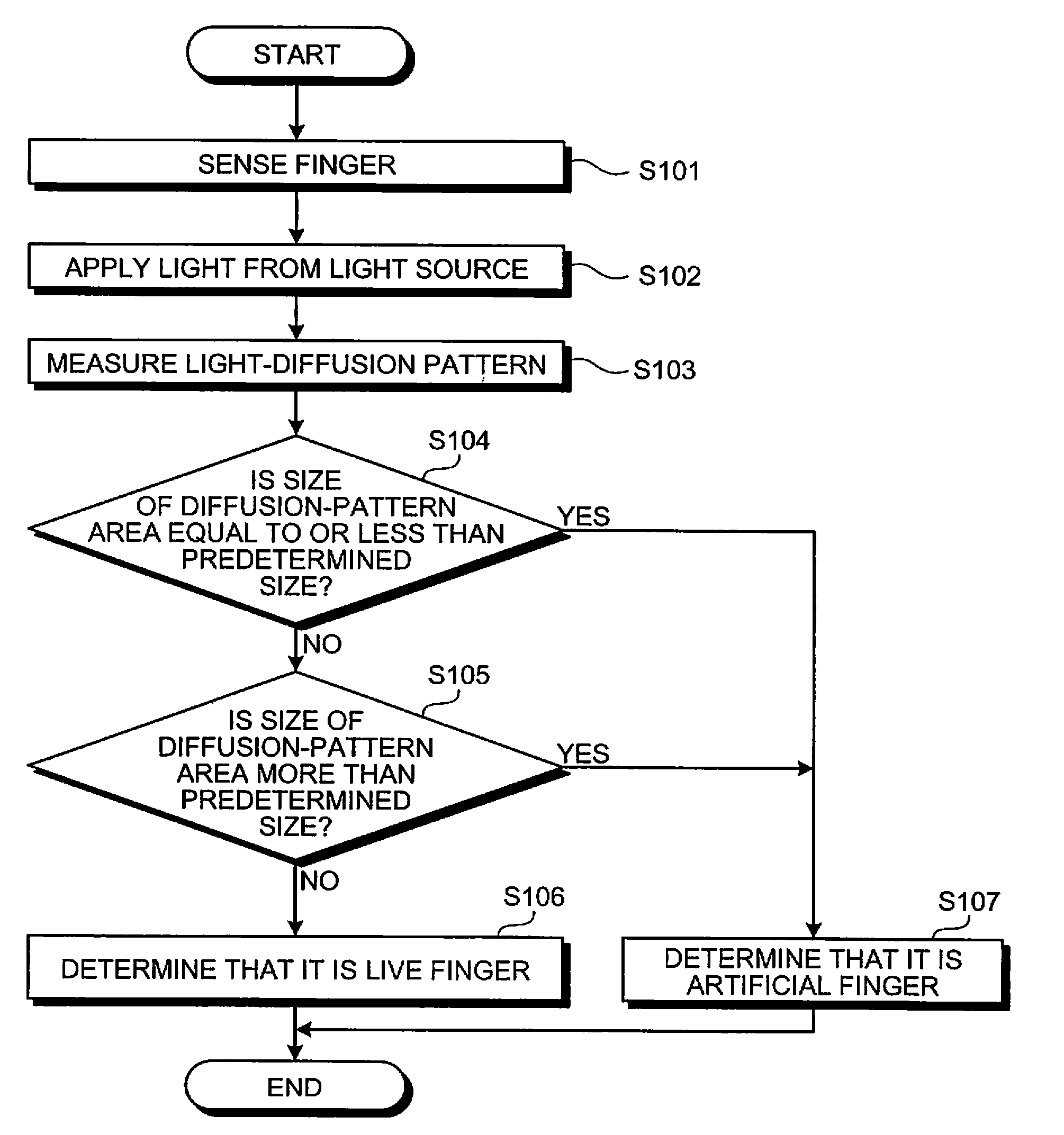
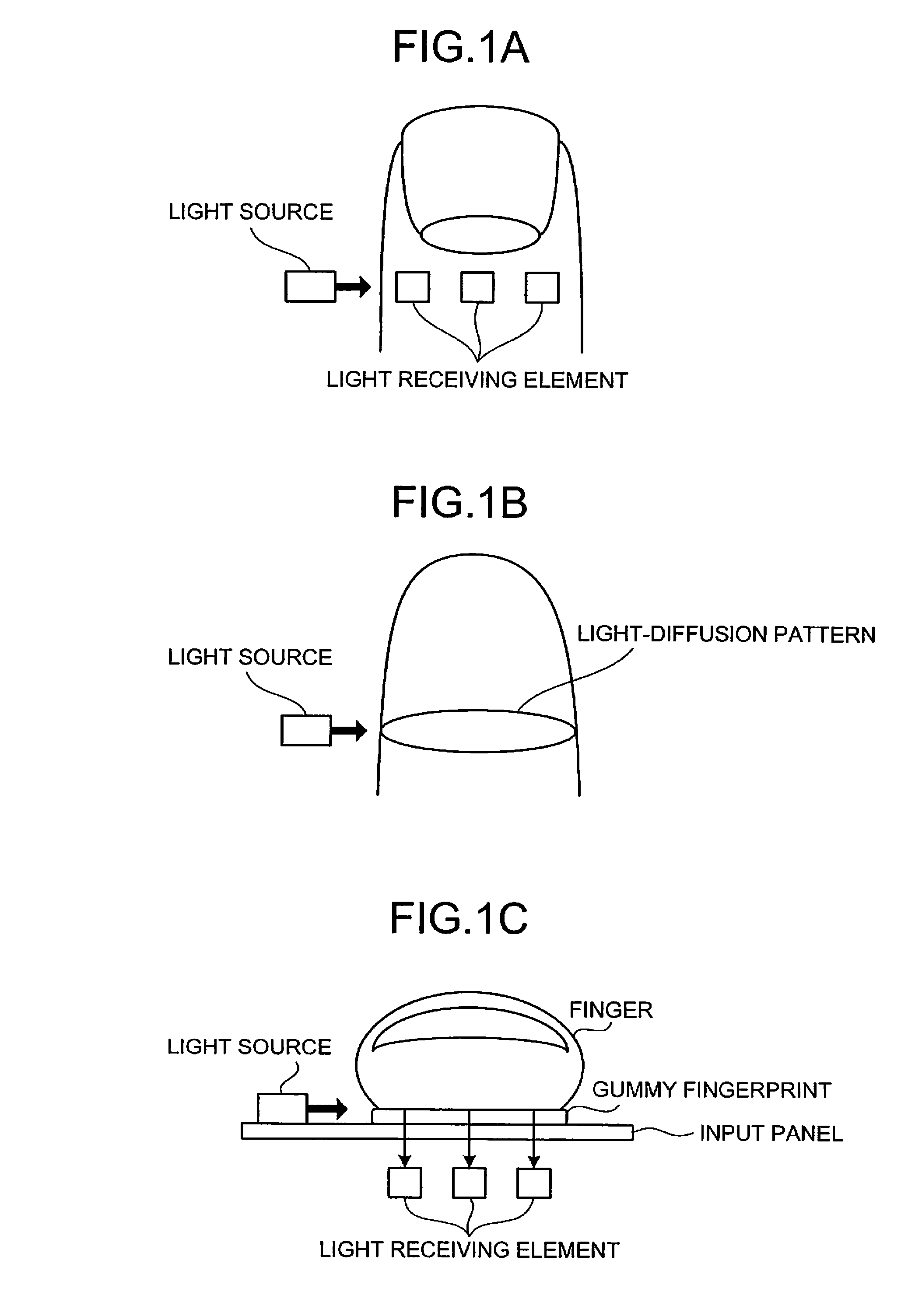
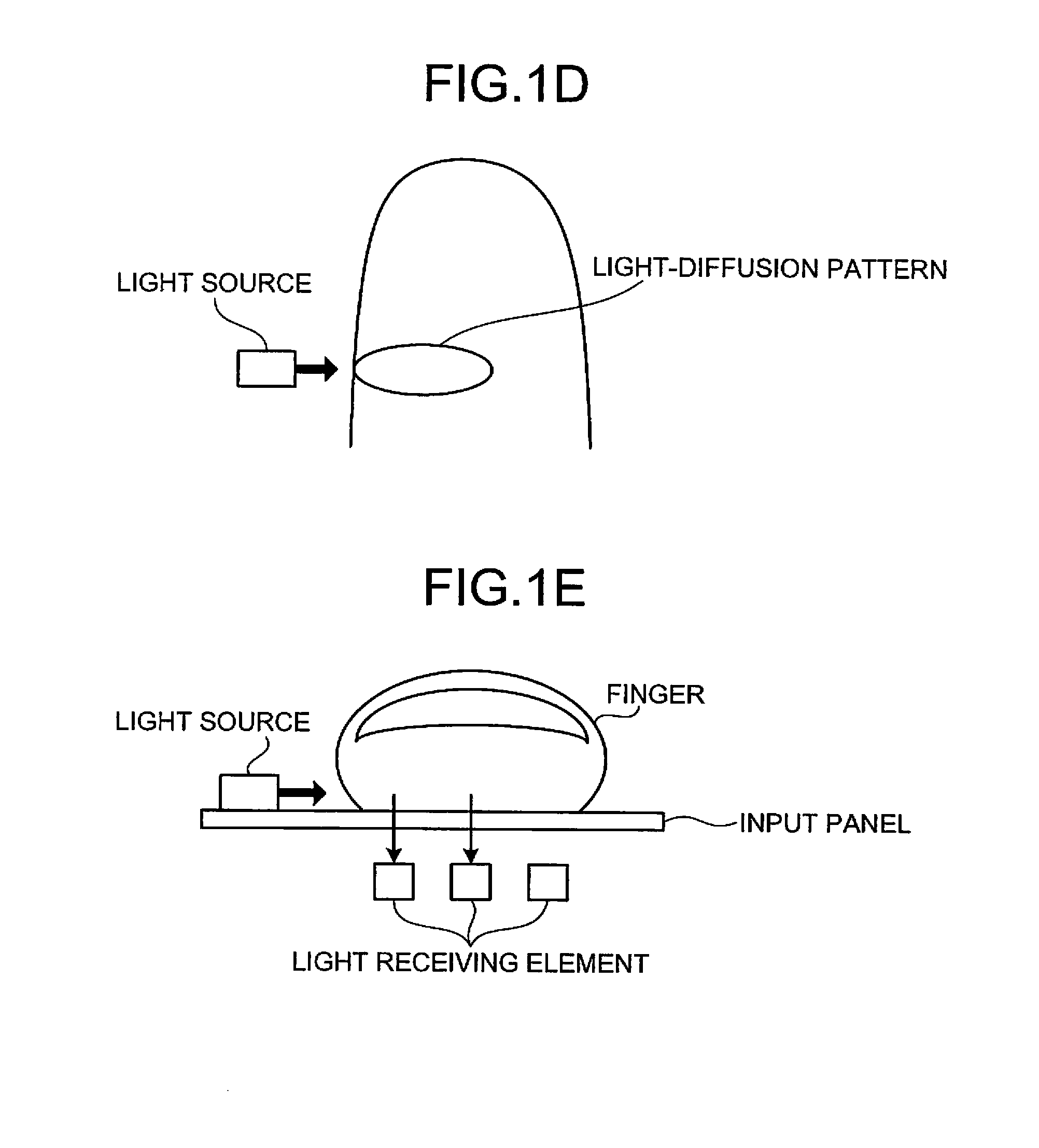
[0059]As described above, it is configured to apply light from a lateral side of the object and measure a diffusion pattern by using a plurality of light receiving elements arranged therein, so that even when thin artificial fingerprint made of such as gummy material is attached to a surface of a real finger, counterfeit can be appropriately detected by using a difference of light transmission characteristics.

[0060]Although, a plurality of light receiving elements are arranged and the light-diffusion pattern is measured by referring from which light receiving element is the light detected, according to the first embodiment, it can be configured to arrange only one light receiving element, change intensity of light applied from the light source at several levels, and determine whether the object is a live-finger by referring at which level of the intensity is the light detected (or not detected).

[0061]According to the first embodiment, an example is explained, which measures the lig...

second embodiment

[0062]According to the present invention, an example is explained with a configuration using the optical fingerprint sensor, which determines whether an object is a live-finger without adding the light receiving elements therein.

[0063]FIG. 7 is a schematic for explaining the concept of a live-finger determining method according to the second embodiment. An optical fingerprint sensor 230 includes a prism 231 used for refracting a fingerprint image toward a direction of an image sensor 233, a lens 232 used for forming an entire image of the image refracted by the optical fingerprint sensor 230 onto the image sensor 233, the image sensor 233, and a light source 234 used for applying light to an object for acquiring image data in good condition.

[0064]The optical fingerprint sensor 230 acquires a first image data of the object to which the light is applied from under the object by the light source 234 and further acquires a second image data of the object to which the light is applied fr...


PUM


Abstract

A fingerprint sensor acquires fingerprint information of an object being in contact. A light source irradiates a light to the object from a lateral side of the fingerprint sensor. A measuring unit measures a diffusion pattern of the light passing through the object. A determining unit determines whether the object is a live finger or an artificial finger based on the diffusion pattern measured by the measuring unit.

Description

BACKGROUND OF THE INVENTION[0001]1. Field of the Invention[0002]The present invention generally relates to a technology for distinguishing a live finger from an artificial finger in a fingerprint authenticating system, even when the artificial finger is made of gummy material.[0003]2. Description of the Related Art[0004]Use of biometric information, such as fingerprints, for performing user authentication is becoming popular. It is said that the user authentication based on the biometric information is more reliable than the conventional method of using passwords or identification (ID) cards; because, while the passwords or the ID cards can be stolen or lost, the biometric information can not be stolen or lost. Even with the biometric information, however, there still is a possibility that a third person can maliciously pass as an authentic person.[0005]In the case of a fingerprint for example, it is not very difficult to prepare an artificial finger that has the same fingerprint as...

Claims


Application Information

Patent Timeline
IPC IPC(8): G06K9/00
CPCG06K9/00906G06K9/00107G06V40/1382G06V40/45G06T1/00G06F18/00
Inventor SHINZAKI, TAKASHINIINUMA, KOICHIRO
Owner FUJITSU LTD
Learn More