
Squirrel-cage rotor

a cage rotor and squirrel technology, applied in the direction of cage rotors, synchronous motors, rotors, etc., can solve the problems of inability to meet the axial length of the cage rotor, the danger of fatigue fracture of the connection rotor bar to the cage ring, etc., to achieve the effect of improving the squirrel cage rotor and reducing the stress of material

Inactive Publication Date: 2007-09-13
SIEMENS AG
View PDF4 Cites 13 Cited by
  • Summary
  • Abstract
  • Description
  • Claims
  • Application Information

AI Technical Summary

Benefits of technology

"The invention relates to an improved squirrel-cage rotor for an electric machine. The improvement is in reducing the stress on the rotor during operation, especially through the use of a flexible squirrel-cage rotor conductor region. This is achieved by creating an open slot in the conductor region, which allows for a reduction in shearing stress. The open slot has an opening in both the radially inner and outer areas of the slot, and can be designed to have a good stiffness with respect to centrifugal forces. The invention also includes a method for geometrically designing the rotor bars to be flexible at the ends, and a method for after-treatment to further optimize the mechanical stress situation. Overall, the invention provides a more efficient and compact squirrel-cage rotor design for electric machines."

Problems solved by technology

As a result of the described problem, the connection rotor bar to cage ring is in danger of encountering a fatigue fracture, depending on the mode of operation of the electric machine.
There is however the drawback of prolongation of the axial length of the squirrel-cage rotor.

Method used


Image

  • Squirrel-cage rotor
  • Squirrel-cage rotor

Examples


Embodiment Construction

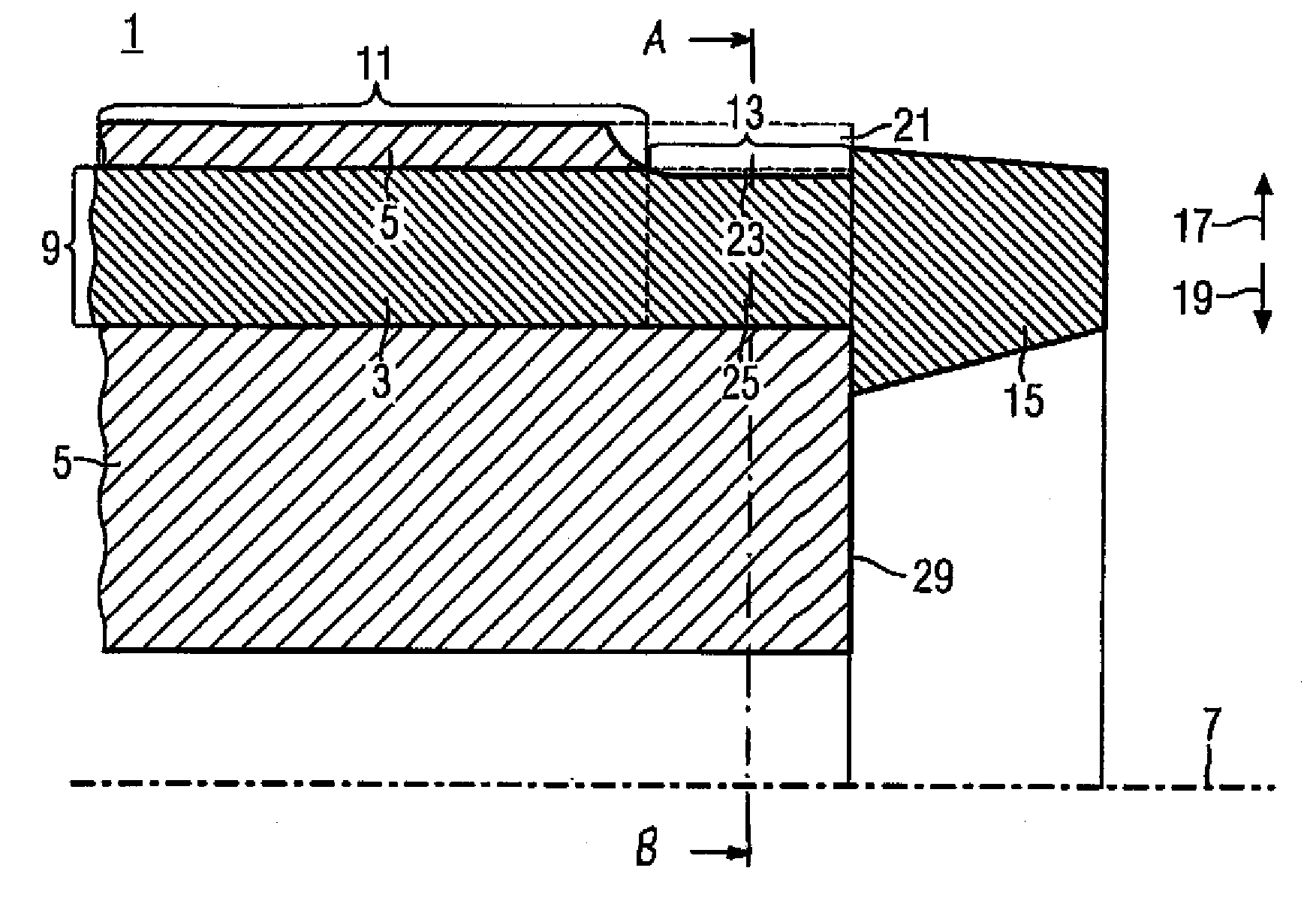
[0032] The illustration of FIG. 1 shows a portion of a cross section of a squirrel-cage rotor 1. The squirrel-cage rotor 1 has a squirrel-cage rotor axis 7. Arranged in surrounding relationship to the squirrel-cage rotor axis 7 is a rotatable carrier 5. The carrier 5 includes in particular magnetic material or is made of such a material. For example, the carrier 5 is a laminated core. The carrier 5 has slots 9 extending axially in relation to the rotation axis of the squirrel-cage rotor. The axial slots 9 are distributed especially rotation-symmetrical in the squirrel-cage rotor 1, i.e. in the carrier 5, wherein the rotation-symmetrical distribution is not shown in FIG. 1. The axial slots 9 can also be designed of beveled configuration.

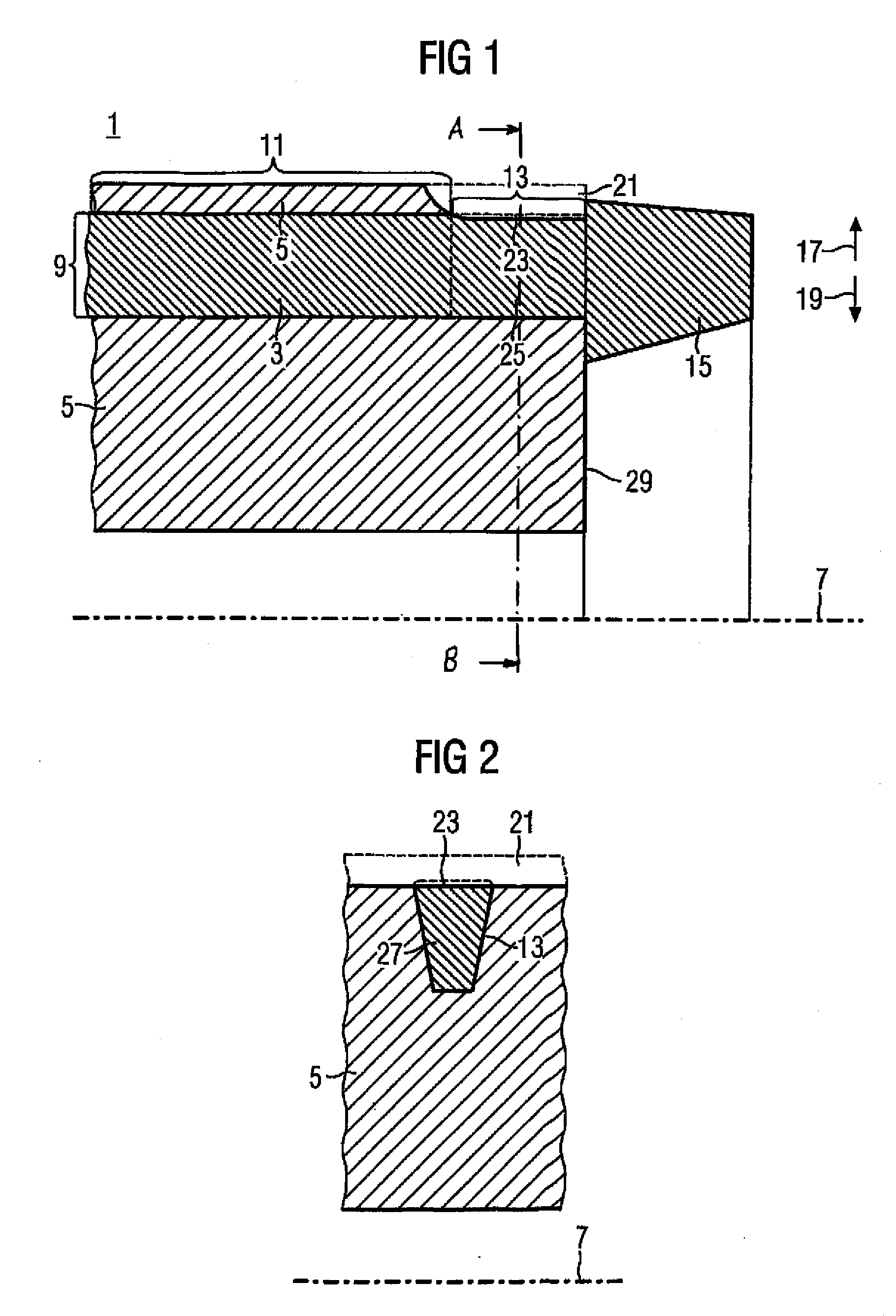
[0033] The slot 9 includes different regions, i.e. portions. A region of the slot 9 is a closed slot portion 11 and another region is an open slot portion 13. A squirrel-cage rotor conductor 3 extends in the area of the closed slot portion 11. The sq...


PUM


Abstract

A squirrel-cage rotor (1) includes squirrel-cage rotor conductors (3) and a carrier (5) for the squirrel-cage rotor conductors (3). The carrier (5) is provided with axial slots (9) in which the squirrel-cage rotor conductors (3) are accommodated. An axial slot (9) includes at least one closed slot portion (11) and an open slot portion (13), with the open slot portion (13) located between the closed slot portion (11) and a cage ring (15). In a method for producing a squirrel-cage rotor (1) having a carrier (5) for squirrel-cage rotor conductors (3), with the carrier (5) having closed slots (9), the squirrel-cage rotor conductors (3) are cast into the slots or are inserted therein as bars, whereupon carrier material is removed in the area of the end surfaces (29) of the carrier (5) in such a way that an open slot portion (13) is formed.

Description

BACKGROUND OF THE INVENTION [0001] The invention relates to a squirrel-cage rotor and to a method of making a squirrel-cage rotor. Squirrel-cage rotors can be used in motors as well as generators. Squirrel-cage rotors find hereby application in particular in asynchronous machines. [0002] Squirrel-cage rotors have squirrel-cage rotor conductors and cage rings, with the cage rings shorting ends of the squirrel-cage rotor conductors. Squirrel-cage rotor conductors and terminal cage rings establish a cage, the short-circuit rotor cage. A cage winding is provided by means of the electric connection between squirrel-cage rotor conductor and cage ring. [0003] The squirrel-cage rotor conductors are implemented for example by metallic rotor bars extending in slots. The slots are preferably axial slots having an axial preferential direction, with an axial slot extending either parallel to the rotation axis of the squirrel-cage rotor or being slanted in a parallel axial preferential direction....

Claims


Application Information

Patent Timeline
Patent Type & Authority Applications(United States)
IPC IPC(8): H02K17/00H02K15/00H02K17/16
CPCB22D19/0054H02K17/165H02K15/0012H02K17/20
Inventor VOGEL, HARTMUT
Owner SIEMENS AG
Learn More