
Recording liquid, liquid cartridge emitting device and liquid emitting method

Inactive Publication Date: 2007-09-13
SONY CORP
View PDF4 Cites 4 Cited by
  • Summary
  • Abstract
  • Description
  • Claims
  • Application Information

AI Technical Summary

Benefits of technology

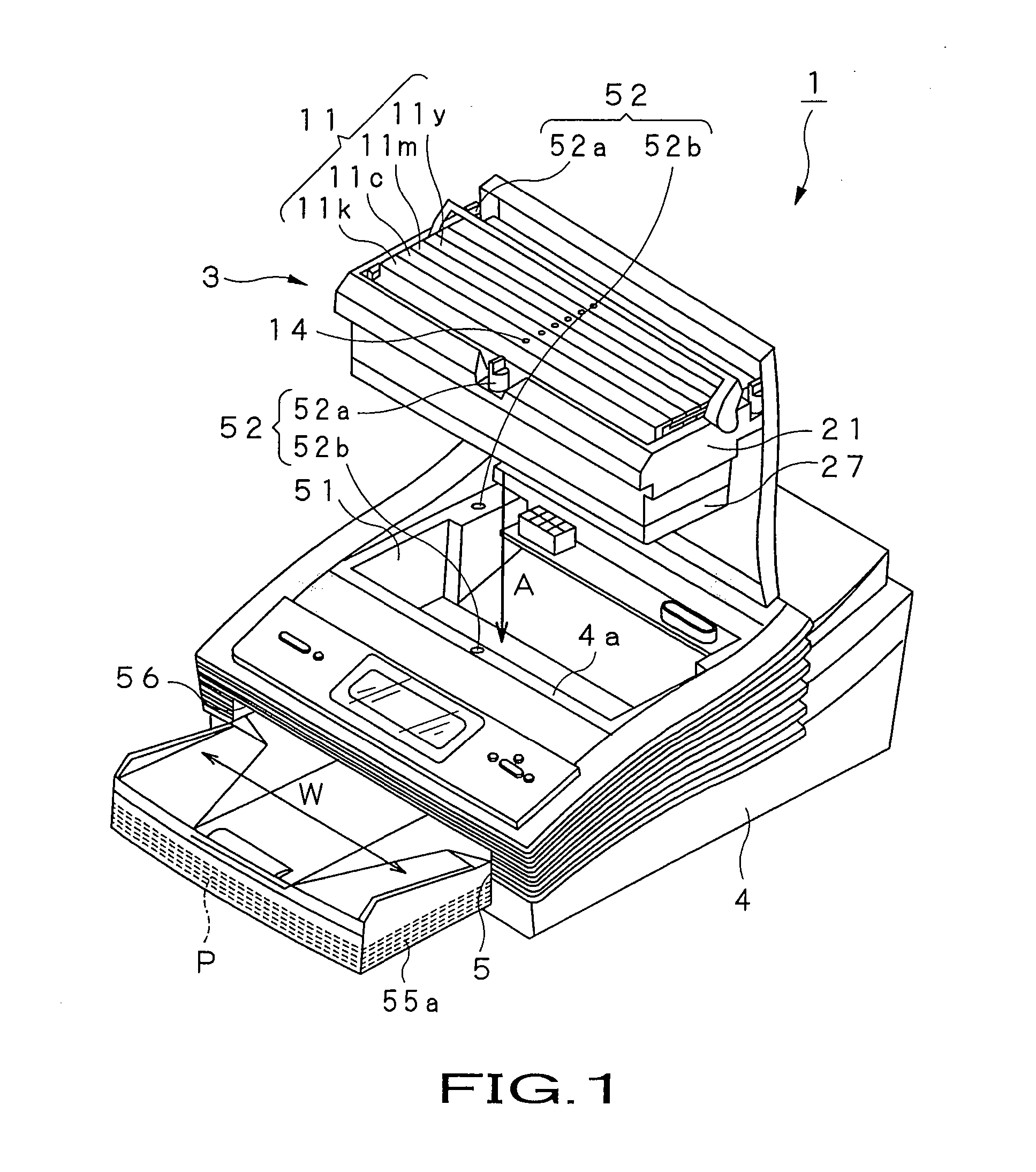
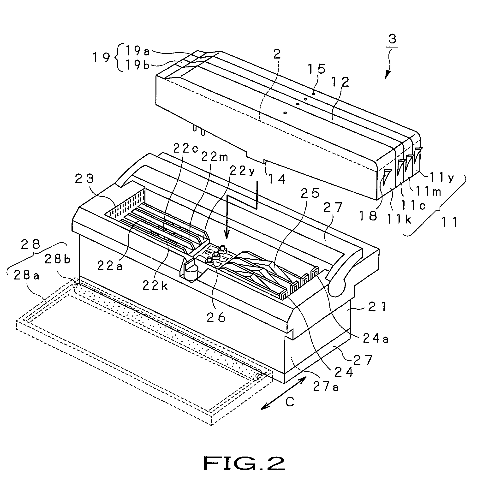
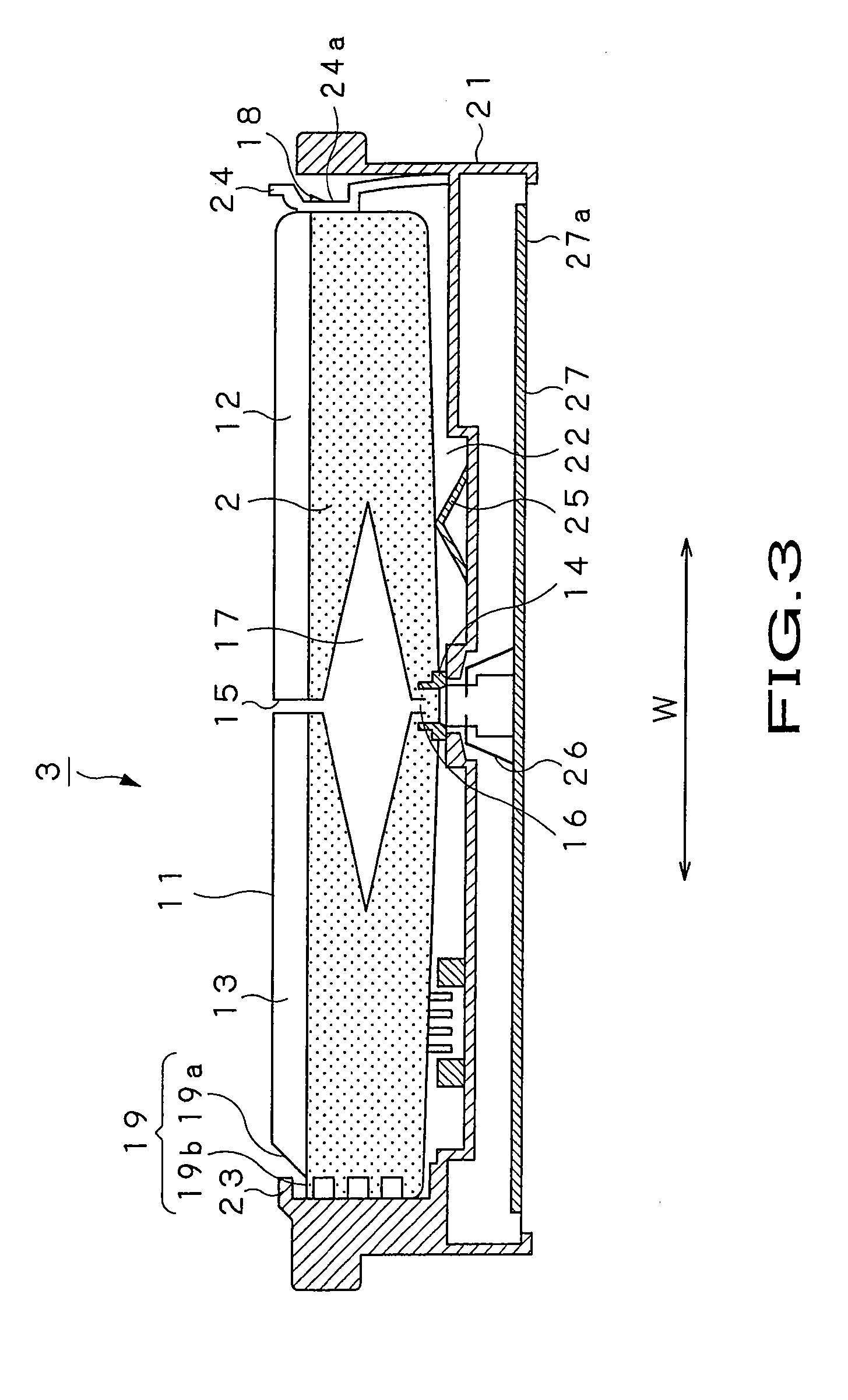
[0003] Among liquid emitting devices for emitting the liquid to a support via an emitting opening, there is a printer device of the ink jet system for recording images or letters / characters. The printer device of the ink jet system lends itself to low running costs, small device size and to formation of multicolor printing images. In a printer device of the ink jet system, the ink as a recording liquid, such as yellow, magenta, cyan or black, is supplied from an ink cartridge to e.g. an ink liquid chamber of a head chip. In this printer device, the ink supplied to e.g. the ink liquid chamber is pressurized by a pressurizing element, such as a resistance heating element, arranged in the ink liquid chamber, and emitted via a small-sized ink emitting opening, that is, a so-called ink nozzle. More specifically, the resistance heating element, arranged in the ink liquid chamber, heats the ink in the ink chamber to generate air bubbles in the ink on the resistance heater to emit the ink via nozzle under the thrusting force exerted by the air bubbles, with the ink then being deposited on a recording sheet, as a support, for printing an image or letters / characters thereon.
[0028] In addition, the recording liquid according to the present invention, containing the surfactant containing the organic compound shown by the above chemical formula 1 in place of the conventional surfactant comprising e.g. acetylene glycols, is less costly than in case of using e.g. acetylene glycols.

Problems solved by technology

However, in the current status of the art, it is difficult to develop an ink having high response properties to the driving frequency in order to keep pace with the increasing printing speed of the printer, that is, the ink designed to cope with a shortened ink emitting interval from the ink nozzle.
However, if the ink viscosity is reduced in this manner, ink emission stability at the time of ink emission from the nozzle is undesirably lowered.
In this case, there may be raised a problem that the deposited ink bleeds along the fiber of the ordinary paper sheet or is not readily dried due to the sizing agent contained in the ordinary paper.
However, with the technique of setting pH of the ink to strong alkalinity, the ink printed on the ordinary paper sheet also becomes strongly alkaline, with the result that an object touching the printed ink is changed in its physical properties.
The technique of using a large quantity of a surfactant suffers a problem that the surface tension of the ink is lowered, while air foams tend to be produced during ink preparation or within an ink liquid chamber, with the so generated air foams not vanishing readily on defoaming.
Moreover, with the present proposal, there is a risk that bleeding occurs severely depending on the sort of the ordinary paper sheet employed.
If the ink is heated to higher than the cloud point of the surfactant, it may be an occurrence that a surfactant is precipitated into the ink to change its physical properties, high image quality printing becomes impossible, or that the shortened emission interval cannot be coped with.
However, the surfactant, comprising an acetylene glycol, as stated in the Japanese Laid-Open Patent Publication 63-139964 or Japanese Patent 3262568, is extremely costly, such that its use in deterrent to the lowering of the production cost of the ink.
On the other hand, the surfactant, comprising acetylene glycols, is susceptible to non-negligible variations in surface activity from one production lot to another, such that the ink quality is not constant.

Method used


Image

  • Recording liquid, liquid cartridge emitting device and liquid emitting method
  • Recording liquid, liquid cartridge emitting device and liquid emitting method
  • Recording liquid, liquid cartridge emitting device and liquid emitting method

Examples


example 1

[0194] In Example 1, 3 parts by weight of C.I. Direct Yellow 86, as a dyestuff serving as a colorant, 70 parts by weight of water as a solvent, 5 parts by weight of glycerin, 10 parts by weight of ethylene glycol, and 10 parts by weight of monobutyl diethyleneglycol, as other solvents, and 2 parts by weight of a non-ionic surfactant of the following chemical formula

where m and n are integers not less than 1, with the total addition amount (m+n) of ethylene oxide (abbreviated below to EO) equal to 2, were mixed together to produce an ink precursor. As the surfactant containing the organic compound shown by the general formula 1, NEXCOAT, manufactured by NIKKO CHEMICALS Co. Ltd., having the addition amount of ethylene oxide changed, was used.

[0195] The ink precursor, obtained with the above composition, was agitated for four hours, in a state heated to 60° C. After the agitation, the ink precursor was compulsorily filtered, as the ink precursor was pressurized with a membrane filt...

example 2

[0196] In Example 2, 4 parts by weight of C.I. Direct Blue 199, as a dyestuff serving as a colorant, 65 parts by weight of water as a solvent, 10 parts by weight of ethylene glycol, 10 parts by weight of ethylene glycol, and 10 parts by weight of triethyleneglycol, as other solvents, and 2 parts by weight of a non-ionic surfactant of the organic compound of the chemical formula 1, similar to that of Example 1, with the total addition amount (m+n) of EO equal to 2, were mixed together to produce an ink precursor. An ink was prepared in the same way as in Example 1, except using the ink precursor.

example 3

[0197] In Example 3, 3 parts by weight of C.I. Acid Red 52, as a dyestuff serving as a colorant, 70.9 parts by weight of water as a solvent, 10 parts by weight of monobutyl triethylene glycol, 5 parts by weight of 2-pyrrolidone, and 10 parts by weight of glycerin, as other solvents, and 0.1 part by weight of a non-ionic surfactant of the organic compound of the chemical formula 1, similar to that of Example 1, with the total addition amount (m+n) of EO equal to 4, were mixed together to produce an ink precursor. An ink was prepared in the same way as in Example 1, except using the ink precursor.


PUM

PropertyMeasurementUnit
Temperatureaaaaaaaaaa
Vapor pressureaaaaaaaaaa
Surface energyaaaaaaaaaa

Abstract

Disclosed is an ink liquid used in a printer device of the ink jet system for recording an image or letters / characters. A surfactant containing an organic compound represented by the following chemical formula 1: where m and n are integers not less than 1, is contained in an ink 2 to prevent blurring or bleeding from being produced at a point of deposition of an ink liquid droplet i.

Description

RELATED APPLICATION DATA [0001] This application is a divisional of U.S. patent application Ser. No. 10 / 522,449, filed Jan. 20, 2005, the entirety of which is incorporated herein by reference to the extent permitted by law, which is the Section 371 National Stage of PCT / JP2004 / 007439. This application claims the benefit of priority to PCT International Application No. PCT / JP2004 / 007439, filed May 25, 2004, and to Japanese Patent Application 2003-152031, filed in the Japanese Patent Office on May 29, 2003, and Japanese Patent Application 2003-344969, filed in the Japanese Patent Office on Oct. 2, 2003, the entirety of which both are also incorporated by reference herein to the extent permitted by law.[0002] This invention relates to a recording liquid for recording on a support, a liquid cartridge holding the recording liquid therein, and to a liquid emitting device and a liquid emitting method for pressurizing the recording liquid by a pressurizing element to emit the liquid in the ...

Claims


Application Information

Patent Timeline
IPC IPC(8): C09D11/02B41J2/01B41J2/015B41J2/14B41J2/175B41J2/19B41M5/00C09D11/00C09D11/326C09D11/328C09D11/38
CPCC09D11/38B41J2/14056B41J2/175C09D11/30
Inventor FUKUDA, TOSHIOYAKURA, YUJINAKAMURA, MASATO
Owner SONY CORP
Learn More