
Decision feedback solution for channels with low signal to noise ratio

Active Publication Date: 2015-07-02
QUALCOMM TECH INT
View PDF2 Cites 5 Cited by
  • Summary
  • Abstract
  • Description
  • Claims
  • Application Information

AI Technical Summary

Benefits of technology

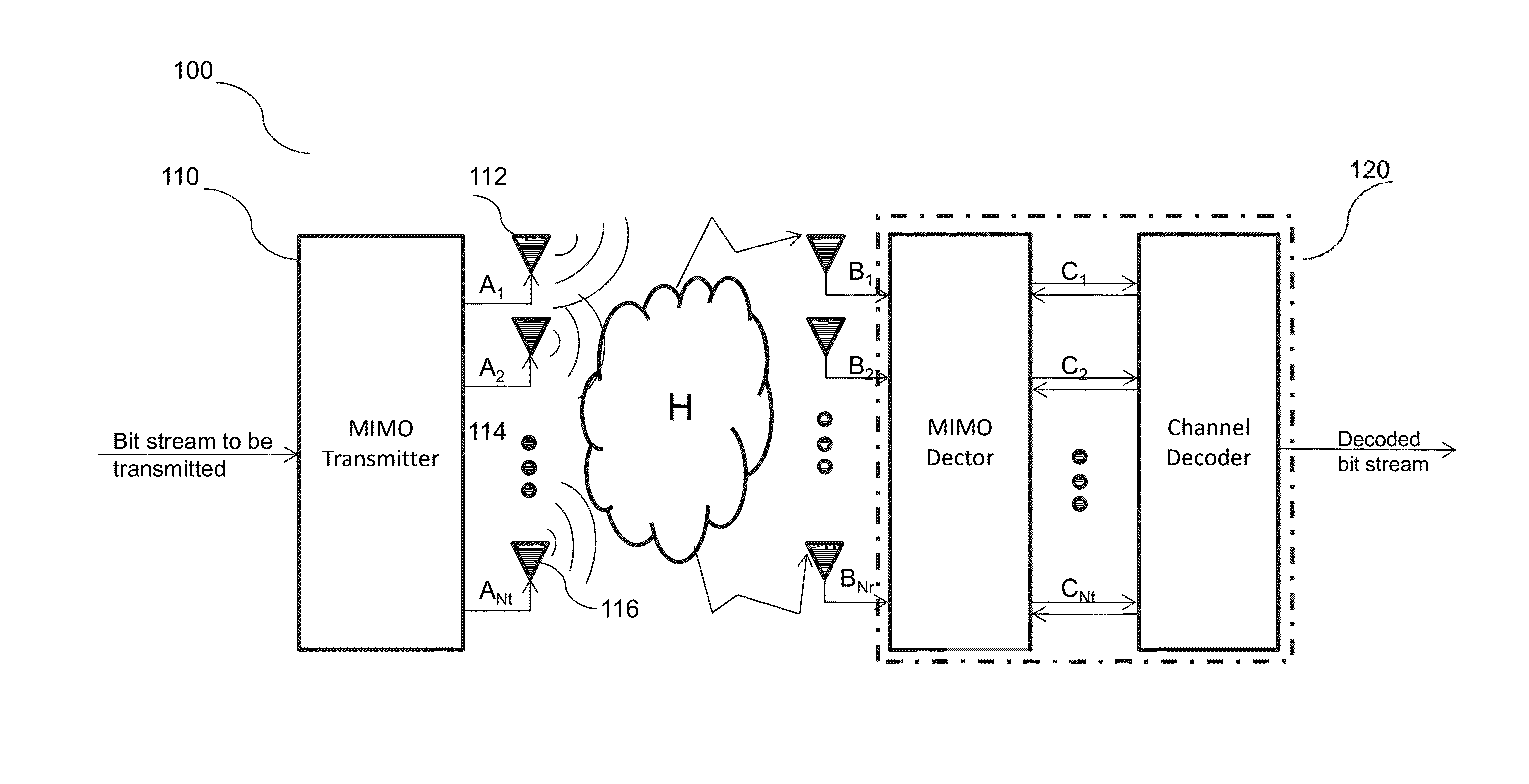
The invention is about a way to design a detector for MIMO wireless communication that is low-complexity and can still perform well even when the channel conditions are poor. It does this by using a combination of linear detection and ML detection, which significantly reduces the complexity of the detector and still performs close to an ML detector. The invention also offers flexibility and low complexity in design and cost reduction in hardware.

Problems solved by technology

However, designing an ML detector is equivalent to solving a non-deterministic polynomial-time (NP)-hard problem, thus impractical to implement due to its exponential complexity.
However, the performance of these conventional linear detectors drops significantly in poor channel conditions.

Method used


Image

  • Decision feedback solution for channels with low signal to noise ratio
  • Decision feedback solution for channels with low signal to noise ratio
  • Decision feedback solution for channels with low signal to noise ratio

Examples


Embodiment Construction

[0017]The invention will now be described in detail with reference to the drawings, which are provided as illustrative examples of the invention so as to enable those skilled in the art to practice the invention. Notably, the figures and examples below are not meant to limit the scope of the invention to a single embodiment, but other embodiments are possible by way of interchange of some or all of the described or illustrated elements. Moreover, where certain elements of the invention can be partially or fully implemented using known components, only those portions of such known components that are necessary for an understanding of the invention will be described, and detailed descriptions of other portions of such known components will be omitted so as not to obscure the invention. Embodiments described as being implemented in software should not be limited thereto, but can include embodiments implemented in hardware, or combinations of software and hardware, and vice-versa, as wi...


PUM


Abstract

This invention is related to a low-complexity MIMO detector in a wireless communication system with near optimal performance. Initial symbol estimation is performed for a transmitted symbol vector. The soft information of the transmitted symbol vector can be more accurately calculated by deemphasizing the LLRs associated with symbols belonging to weak channels that may suffer from poor initial estimation. By combining aspects of both the linear detection and the ML detection, the complexity of the proposed detector becomes orders of magnitude lower than that of a ML detector, but the performance is very close to that of an ML detector.

Description

FIELD OF THE INVENTION[0001]The invention is related to wireless communication systems, and more particularly, to methods and apparatus of implementing low-complexity MIMO detectors in a wireless communication system with near maximum likelihood performance even under poor channel conditions.BACKGROUND OF THE INVENTION[0002]Having evolved rapidly and steeply in the past two decades, the wireless communication systems now offer a wide variety of services such as multimedia communications, web browsing, audio and video streaming, online game playing, etc. Not surprisingly, the number of users accessing these services has also increased drastically. The resulting increase in data traffic together with the scarceness of wireless spectrum resources has made high efficiency data transmission an essential factor in the design of wireless communication systems.[0003]The use of multiple-input-multiple-output (MIMO) techniques has thus become the new frontier of wireless communications. The M...

Claims


Application Information

Patent Timeline
IPC IPC(8): H04L1/00H04L27/26H04B7/04
CPCH04L1/0054H04L27/265H04B7/0413H04L1/0048H04L25/03891H04L25/067H04L25/03318
Inventor TONG, FEIWAN, HONGLINDSKOG, ERIK
Owner QUALCOMM TECH INT
Learn More