
Method and apparatus for strain monitoring of printed circuit board assemblies

a technology for printed circuit boards and assemblies, applied in the direction of apparatus for force/torque/work measurement, individual semiconductor device testing, instruments, etc., can solve the problems of time and other delays and costs, the inability to use the printed circuit board assemblies for commercial products, and the cost of mounting strain gauges on the printed circuit board

Inactive Publication Date: 2007-09-06
CISCO TECH INC
View PDF22 Cites 16 Cited by
  • Summary
  • Abstract
  • Description
  • Claims
  • Application Information

AI Technical Summary

Benefits of technology

[0005] In contrast to the above-described conventional monitoring methods for detecting strain, improved techniques are directed to monitoring a strain by a strain detector formed of a non-ductile material. Failure can be determined visually or electrically and the proposed method does not require expensive strain gages or limit sampling to merely a sample of the printed circuit board assemblies manufactured.

Problems solved by technology

Unfortunately, there are deficiencies to the above-described method of using strain gages to determine what caused the strain-induced failure.
These deficiencies include the expense of mounting the strain gages on the printed circuit board, the time and other delays and cost resulting from having wires extending from the strain gage interfering with the assembly process.
Furthermore the printed circuit board assemblies (PCBA) cannot be used for commercial products for numerous reasons including the strain gage and associated wires' appearance and interference with the customer's final use.

Method used


Image

  • Method and apparatus for strain monitoring of printed circuit board assemblies
  • Method and apparatus for strain monitoring of printed circuit board assemblies
  • Method and apparatus for strain monitoring of printed circuit board assemblies

Examples


Embodiment Construction

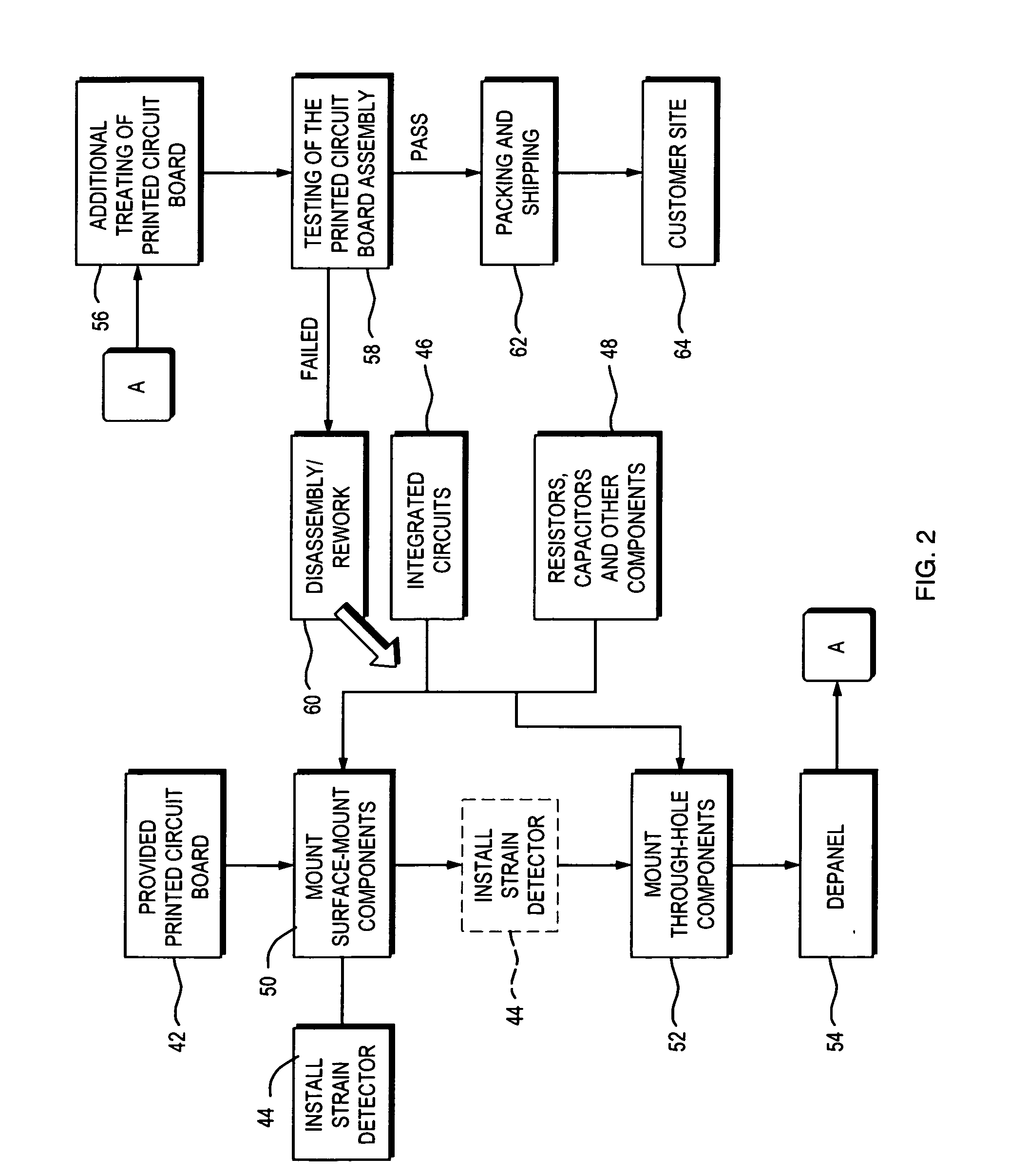
[0025] An improved method of testing / monitoring a printed circuit board assembly (PCBA) for strain-induced failures utilizing at least one strain detector mounted on the printed circuit board where the strain detector is formed of a non-ductile material. The strain detector has a narrowed portion to define a weakest link for failure at a pre-defined strain range. The failure of the strain detector and the reaching of a strain in the critical strain range can be determined visually or electrically. Accordingly, the conventional approach of using a strain gage with its associated cost and limited to only a sampling of the PCBAs is unnecessary.

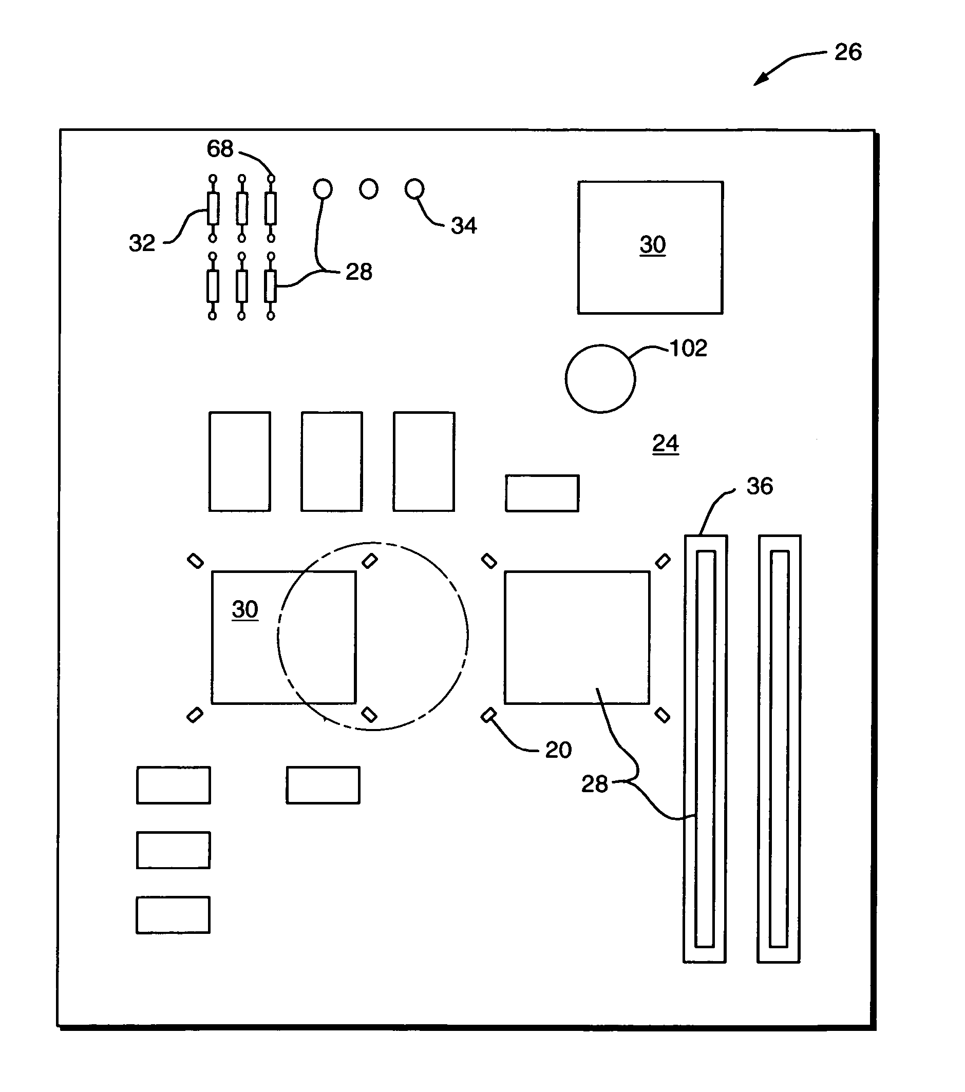
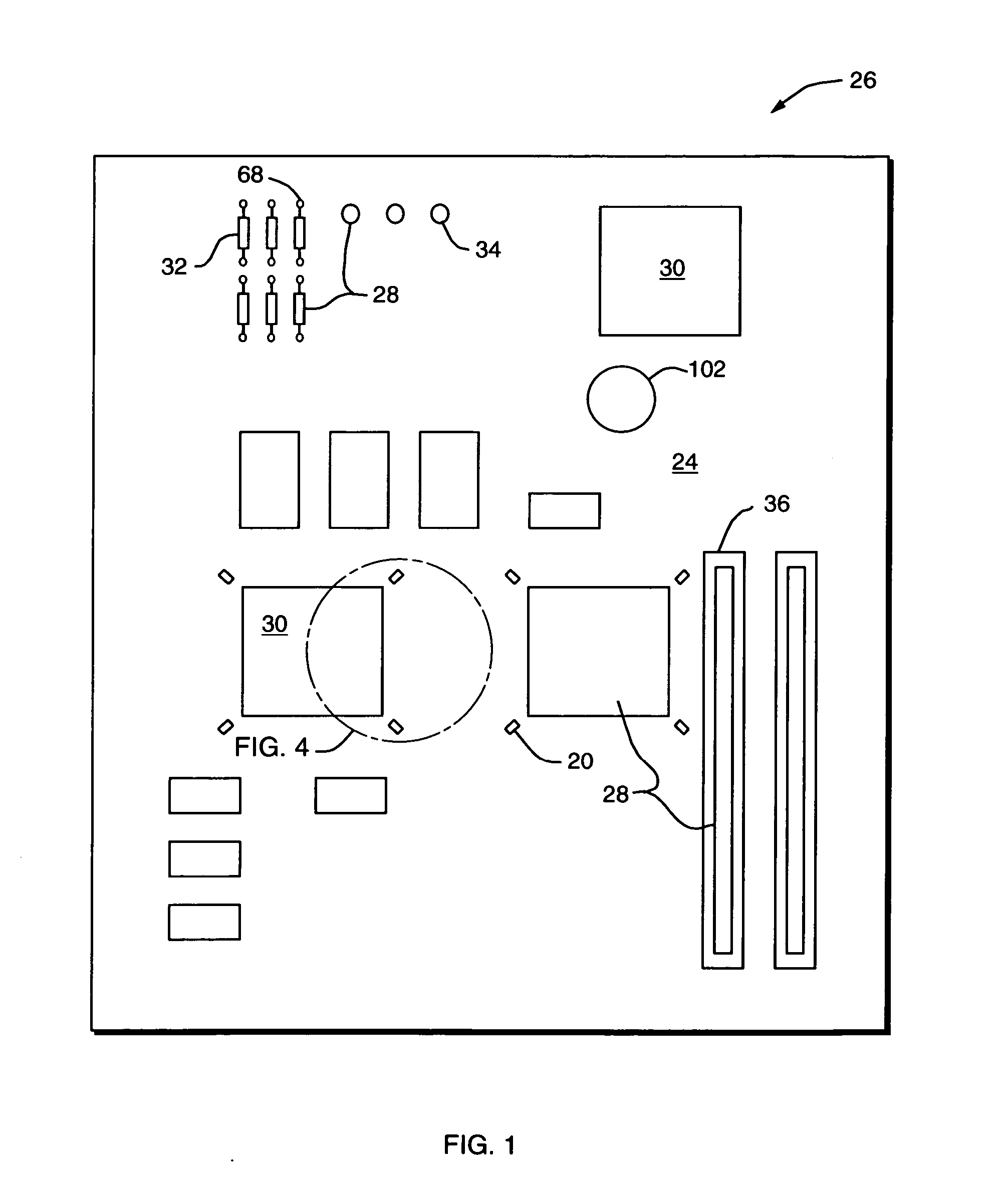
[0026] When referring to the drawing in the description which follows, like numerals indicate like elements. FIG. 1 shows a strain detector 20 located on a printed circuit board (PCB) 24 of a printed circuit board assembly (PCBA) 26.

[0027] Referring to FIG. 1, the printed circuit board assembly (PCBA) 26 is shown. The PCBA 26 has a series of co...


PUM


Abstract

A technique of monitoring strain on a printed circuit board assembly involves the use of a strain detector mounted on a printed circuit board. The strain detector is formed of a non-ductile material. The strain detector has a narrowed portion forming a weak link that has a characteristic of breaking when a critical strain limit is exceeded. The method of monitoring can include visual or electrical inspection. The electrical inspection can include having a strain monitoring device. The strain monitoring device has a timer connected to at least one strain detector and a memory for storing results connected to the timer. The capacitance of at least one of the strain detectors is sampled and any change in capacitance is recorded to the memory. In one embodiment, a time stamp occurs in the memory based on when an electrical property changes across at least one of the strain detectors.

Description

BACKGROUND [0001] Printed circuit board assemblies (PCBAs) are used in numerous equipment including computers, telephones, major appliances, vehicles such as automobiles, trains, and planes, and toys, etc. The printed circuit boards (PCBs) are getting more crowded with items such as integrated circuits, resistors, heat sinks, and other components. [0002] A series of processes is required to create the printed circuit board and add the components to the printed circuit board to create the completed printed circuit board assembly. Unfortunately the printed circuit board assembly manufacturing process does not result in each of the printed circuit board assemblies working perfectly. The components and the printed circuit board, while not expensive individually, together produce an expensive item. In addition, there is a time and cost factor in determining which printed circuit board assembly (PCBA) works properly and which PCBA does not work properly. In some situations, the cost and t...

Claims


Application Information

Patent Timeline
Patent Type & Authority Applications(United States)
IPC IPC(8): G01R31/26
CPCG01R31/2817H05K1/0268H05K2203/163H05K2201/10151H05K1/0271
Inventor AHMAD, MUDASIRTENG, SUE
Owner CISCO TECH INC
Learn More