
Apparatus for and method of capturing radiation image

a radiation image and apparatus technology, applied in the field of apparatus for and apparatus for capturing radiation images, can solve the problems of large error in the determination of radiation dosage, temperature compensation devices that cannot provide highly accurate temperature compensation, and difficult selection of temperature compensation devices capable of handling variations in characteristics, so as to achieve the effect of accurately determining radiation dosag

Inactive Publication Date: 2007-08-30
FUJIFILM HLDG CORP +1
View PDF7 Cites 16 Cited by
  • Summary
  • Abstract
  • Description
  • Claims
  • Application Information

AI Technical Summary

Benefits of technology

[0010]It is a general object of the present invention to provide an apparatus for and a method of capturing a radiation image while highly accurately determining the radiation dosage, so as to control a radiation source regardless of temperature-dependent and time-dependent characteristic changes in the circuit components thereof.

Problems solved by technology

However, since the radiation dosage is determined after a low voltage signal has been amplified at a high magnification, the image capturing system having such an automatic exposure control function is problematic in that a temperature-dependent characteristic change of the circuit components tends to cause a large error in the determined radiation dosage.
Therefore, if the temperature compensating device is not thermally coupled adequately to the circuit component whose temperature-dependent characteristic change is to be compensated for, then the temperature compensating device cannot provide highly accurate temperature compensation.
In addition, the circuit component has its own time-variable characteristics, and as a practical matter, it is difficult to select a temperature compensating device that is capable of handling variations in characteristics.

Method used


Image

  • Apparatus for and method of capturing radiation image
  • Apparatus for and method of capturing radiation image
  • Apparatus for and method of capturing radiation image

Examples


Embodiment Construction

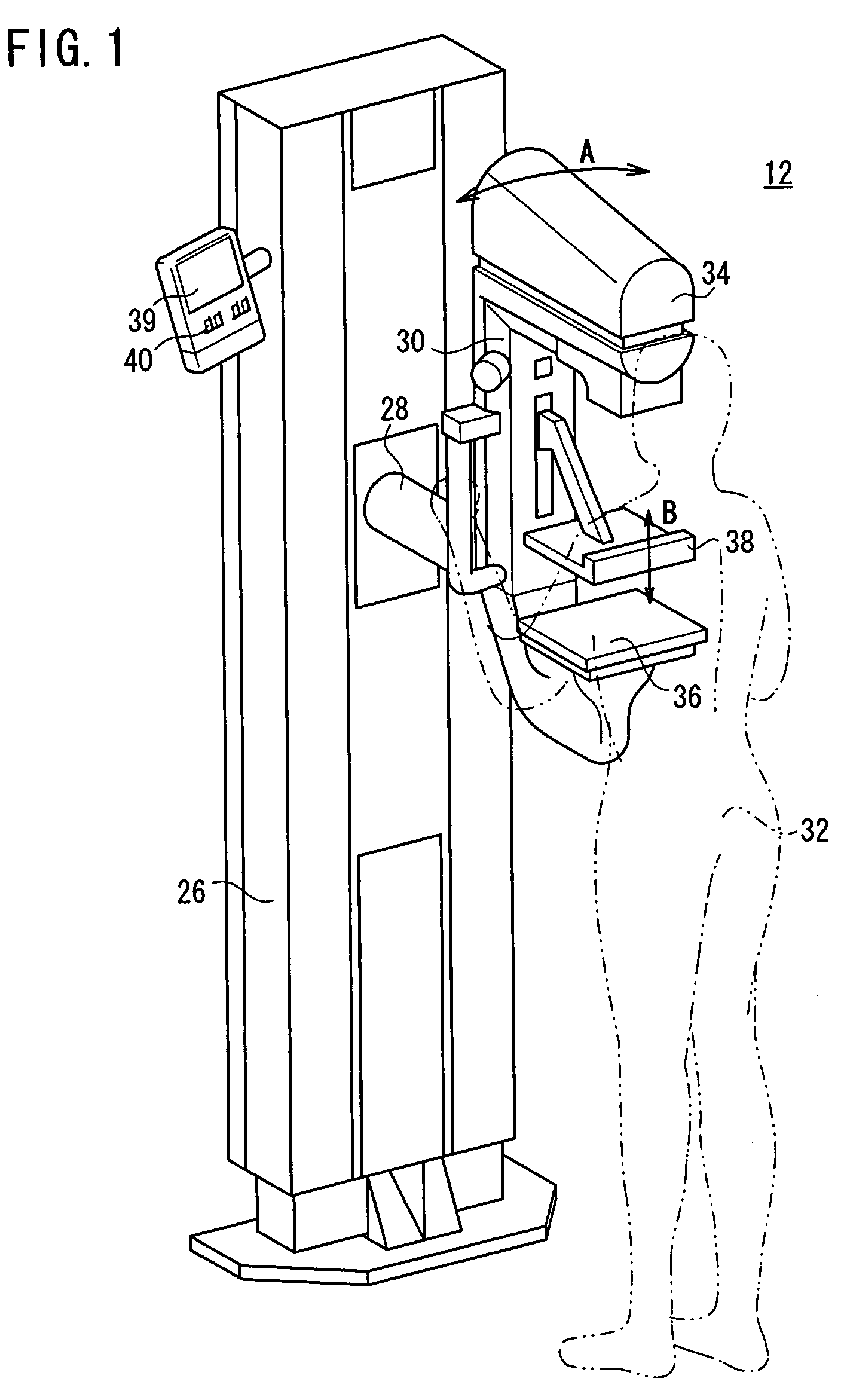
[0022]FIG. 1 shows in perspective a mammographic system 12 to which an apparatus for and method of capturing a radiation image according to an embodiment of the present invention are applied.

[0023]As shown in FIG. 1, the mammographic system 12 has an upstanding base 26, a vertical arm 30 fixed to a horizontal swing shaft 28 disposed substantially centrally on the base 26, a radiation source housing unit 34 storing a radiation source for applying radiation to a subject 32 and which is fixed to an upper end of the arm 30, an image capturing base 36 housing a solid-state detector for detecting radiation that has passed through the subject 32 and which is fixed to a lower end of the arm 30, and a presser plate 38 for pressing and holding the subject's breast against the image capturing base 36.

[0024]When the arm 30, to which the radiation source housing unit 34 and the image capturing base 36 are secured, is angularly moved about the swing shaft 28 in a direction indicated by the arrow ...


PUM


Abstract

Before a radiation image is captured, a rate of change of an output signal from an integrator, during a given period of time after the integrator has been reset and until a radiation start signal is supplied, is calculated. An offset voltage signal at a desired time is calculated using the rate of change, and is supplied to a voltage correcting circuit. An output signal from the integrator after a radiation X has started being applied to a subject is corrected based on the calculated offset voltage signal. The corrected output signal from the integrator is supplied to an X-ray tube controller for controlling application of the radiation X to the subject.

Description

BACKGROUND OF THE INVENTION[0001]1. Field of the Invention[0002]The present invention relates to an apparatus for and a method of capturing a radiation image by emitting radiation from a radiation source and applying the emitted radiation to a subject, and for controlling the radiation source based on the dose of radiation applied to the subject.[0003]2. Description of the Related Art[0004]In the medical field, for example, it has been customary to apply radiation to a subject and to detect the amount of radiation that has passed through the subject with a radiation detector, or to guide the radiation that has passed through the subject directly to an X-ray film or the like, thereby forming a radiation image of the subject for diagnostic purposes.[0005]For obtaining a radiation image suitable for image interpretation and diagnosis, a tube voltage, a tube current, and a radiation application time are established as appropriate exposure conditions, depending on the body region to be i...

Claims


Application Information

Patent Timeline
IPC IPC(8): H05G1/44A61B6/04
CPCA61B6/0414A61B6/502H05G1/30A61B6/544A61B6/542
Inventor NAKAYAMA, HIROKISENDAI, TOMONARI
Owner FUJIFILM HLDG CORP
Learn More