
Break-free safety release buckle and fastener

a safety release buckle and buckle technology, applied in the direction of clothing, applications, household appliances, etc., can solve the problems of unsuitable use in other applications, and achieve the effects of reducing manufacturing costs, facilitating adaptation, and facilitating application flexibility

Inactive Publication Date: 2007-08-30
DUX FIN
View PDF10 Cites 12 Cited by
  • Summary
  • Abstract
  • Description
  • Claims
  • Application Information

AI Technical Summary

Benefits of technology

[0004] It is one object of the present invention to provide a safety release mechanism which is adaptable to the design of many known buckles and fasteners, such that the release member is a combined part of the fastener, providing an inexpensive compact safety release fastener which can also be selectively attached, removed, or adjusted for length and fit by conventional means.
[0005] It is an additional object to provide a safety release fastener which can easily be adapted in a tamper-proof design, such that a universal separating member can be adapted by the manufacturer to provide various pre-determined fixed release tensions in the same device, the...

Problems solved by technology

Most such devices are constructed with a low tension release, which makes them unsuited for use in other applications which require them to hold under a greater release tension.

Method used


Image

  • Break-free safety release buckle and fastener
  • Break-free safety release buckle and fastener
  • Break-free safety release buckle and fastener

Examples


Embodiment Construction

[0023] The present invention will generally be constructed of semi-rigid material similar to that used in the manufacture of plastic fasteners and buckles which are generally formed by injection molding, although other suitable material and methods of forming may be used.

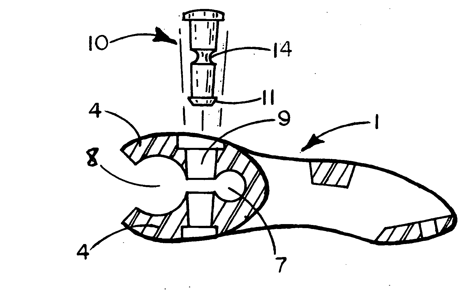
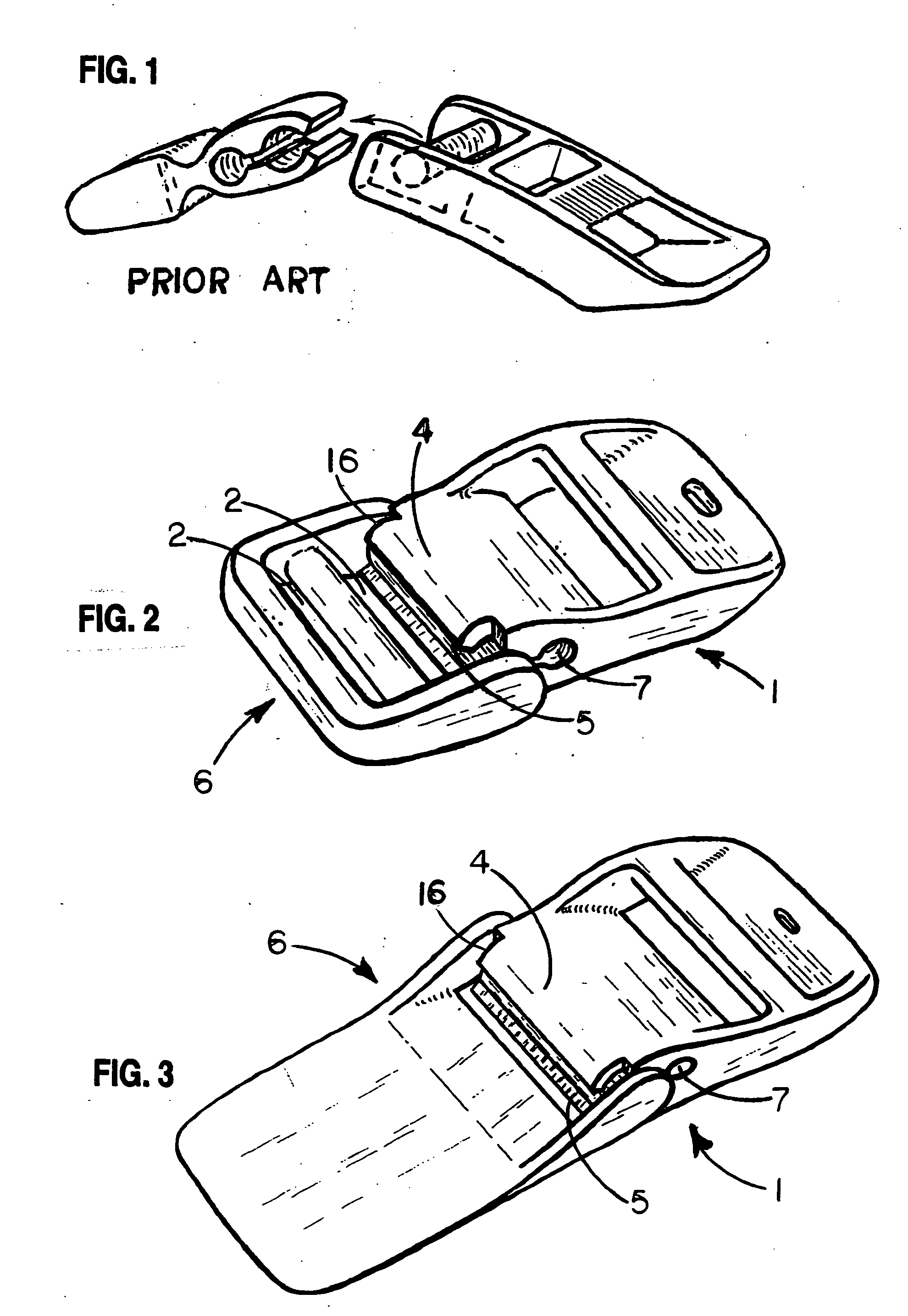
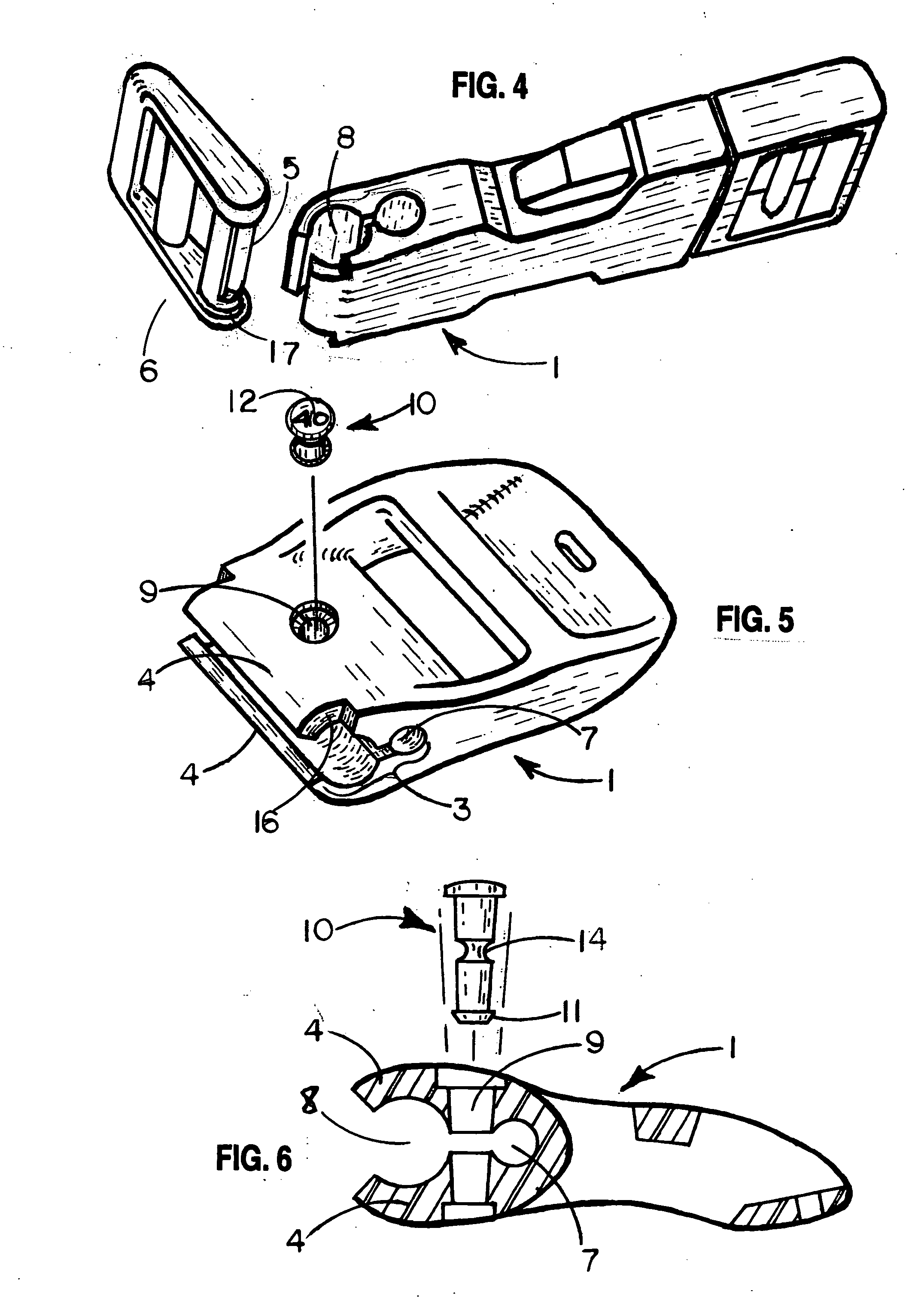
[0024] In the following description major parts of the assembly will be referred to as a release member 1 and a fastening link 6. While the jaws 4, stud 5, and related structures can be incorporated on either buckle portion, in the preferred and illustrated embodiment the jaws 4 will be incorporated as part of the primary buckle member to which the break free invention is adapted. In this manner, when the rivet 10, bridge 13, or other such limiting device is broken or the jaws 4 eventually fail, the broken or failed members can be easily replaced as part of a replacement release member. If the jaws were reversed, as being part of the fastening link, it would be necessary to remove stitching or other fastenings whic...


PUM


Abstract

A quick-release fastening device is disclosed. The device includes a first fastening component having upper and lower surfaces and first and second end portions. A pair of first and second elongated jaw elements are disposed on the first component first end portion and form a channel-like socket therebetween. The jaws define a gripping mechanism having an elongated jaw opening accessing the socket. The first jaw element has a length dimension less than the second jaw element. A tubular pocket is defined in the first member first end portion adjacent the channel-like socket to form a pivot point for the jaw elements. A second fastening component has first and second end portions, the second fastening component first end portion being adapted for releasable engagement with the first fastening component first end portion. Finally, a stud is mounted in the second fastening component first end portion. The stud is sized for releasable engagement within the channel-like socket and further includes an elongated cut-out portion which forms a slot along a substantial portion of the length of the stud, the slot being sized to match the first jaw element to enhance engagement of the stud within the socket without affecting release resistance of said stud imposed by said jaw elements.

Description

RELATED PATENT APPLICATIONS [0001] This application is related to U.S. provisional patent application No. 60 / 535,026, filed Jan. 8, 2004.BACKGROUND OF THE INVENTION [0002] This invention relates generally to safety release mechanisms, quick release mechanisms, and fasteners which are designed to free a wearer (including humans and other animals) from equipment, harnesses, and bindings of such equipment which secure it on or about the wearer. These devices are also appropriate for use on luggage and other items which could become entangled with other equipment such as in automated handling systems, conveyers, etc. In many situations items attached to or around the wearer can become caught or entangled, thereby trapping and subjecting the wearer or equipment to potential injury including possible fatal injury or equipment damage which could occur if the worn device and / or harness remained firmly connected. Specifically, this invention is related to fasteners, buckles, and tension rele...

Claims


Application Information

Patent Timeline
IPC IPC(8): A44B11/00
CPCY10T24/4736A44B11/2542
Inventor JOHNSON, CARROLL L.
Owner DUX FIN
Learn More