
Synchronization apparatus and method for improving timing estimation performance in OFDM-FDMA/CDMA/TDMA system

a timing estimation and synchronization apparatus technology, applied in multi-frequency code systems, door/window protective devices, amplitude demodulation, etc., can solve the problems of large probability, received signals cannot be correctly recovered, and standard cannot meet the requirement of a highly increasing data rate, etc., to achieve the effect of improving timing estimation performan

Inactive Publication Date: 2007-08-23
INHA UNIV RES & BUSINESS FOUNDATION
View PDF5 Cites 31 Cited by
  • Summary
  • Abstract
  • Description
  • Claims
  • Application Information

AI Technical Summary

Benefits of technology

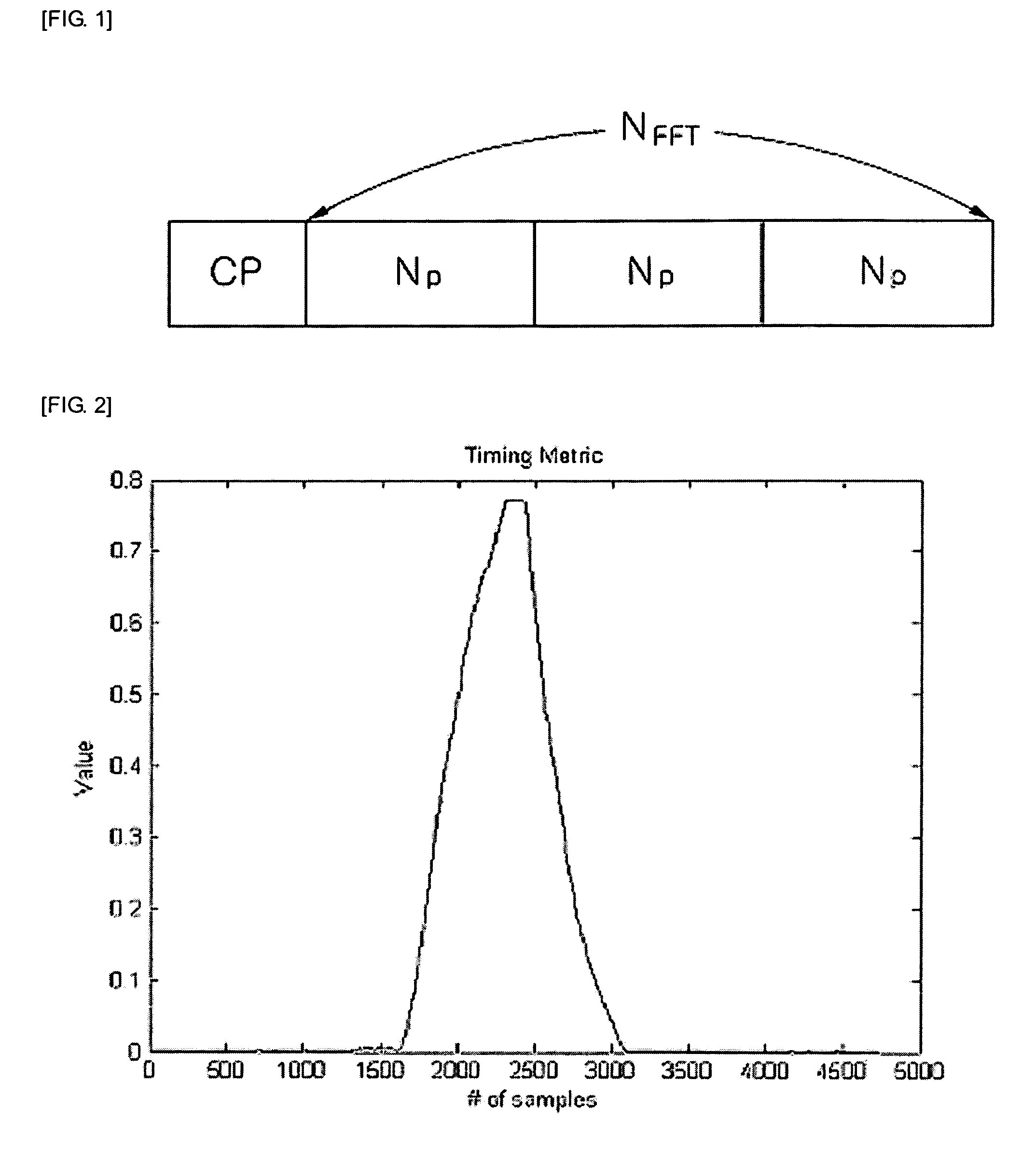
[0027]An advantage of the present invention is that it provides a synchronization apparatus and method for improving timing estimation performance in an OFDM-FDMA / CDMA / TDMA system, which can correctly estimate symbol timing. Specifically, a timing metric generating a peak at a correct symbol timing position is obtained using a preamble structure in which patterns are repeated by a predetermined number of times after IFFT process, thereby acquiring a correct timing position.
[0028]Additional aspect and advantages of the present general inventive concept will be set forth in part in the description which follows and, in part, will be obvious from the description, or may be learned by practice of the general inventive concept.
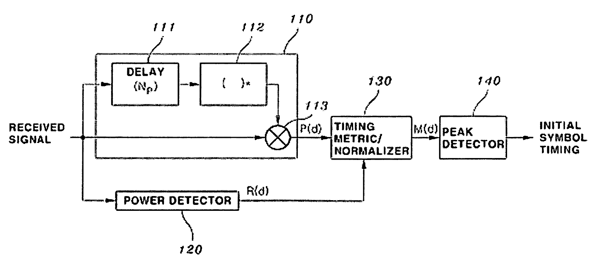
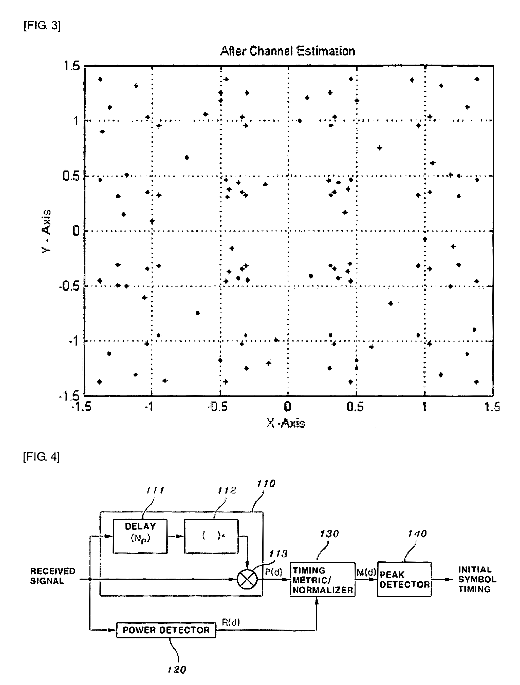
[0029]According to an aspect of the invention, there is provided a synchronization apparatus for symbol timing synchronization of an OFDM-FDMA / CDMA / TDMA system having a preamble structure in which patterns are repeated three times in time domain. The synchronization apparatus includes: an auto-correlator for calculating an auto-correlation value of a received signal and a signal delayed by Np (NP=NFFT / 3 where NFFT is an FFT size); a power detector for calculating a power of the received signal in order to normalize the auto-correlation value; a timing metric / normalizer for normalizing the auto-correlation value by diving the auto-correlation value by the calculated power to obtain a timing metric; and a peak detector for finding a peak value of the timing metric by measuring one frame while moving by one sample from an arbitrary starting point and estimating a frame starting position and an initial symbol timing.
[0030]The auto-correlator calculates an auto-correlation length using (2Np-1)+Ncp (Np: NFFT / 3, Ncp: length of a guard interval), considering the preamble characteristic that the patterns are repeated in the time domain.
[0031]The auto-correlator calculates the auto-correlation value using a following equationP(d)=∑m=0(2Np-1)+Ncpr(d+m)r*(d+m+Np)where r(d) denotes the received signal, d denotes a sample index of the received signal, and m denotes a correlation length index (0-(2Np-1)+Ncp).
[0032]The initial symbol timing is set to a position determined by adding the position where the timing metric has a peak value to the length of the guard interval and subtracting the maximum value of the expected channel delay spread from the result value.

Problems solved by technology

This standard, however, could not meet the requirement of a highly increasing data rate.
Consequently, the received signals cannot be correctly recovered.
However, there is a great probability that a wrong frame timing is acquired out of the guard interval due to the uncertainty at a boundary portion of the timing metric.
However, when the timing estimation error is large, the channel estimator cannot correct the entire error.

Method used


Image

  • Synchronization apparatus and method for improving timing estimation performance in OFDM-FDMA/CDMA/TDMA system
  • Synchronization apparatus and method for improving timing estimation performance in OFDM-FDMA/CDMA/TDMA system
  • Synchronization apparatus and method for improving timing estimation performance in OFDM-FDMA/CDMA/TDMA system

Examples


Embodiment Construction

[0042]Reference will now be made in detail to the embodiments of the present general inventive concept, examples of which are illustrated in the accompanying drawings, wherein like reference numerals refer to like elements throughout. The embodiments are described below in order to explain the present general inventive concept by referring to the figures.

[0043]Hereinafter, preferred embodiments of the present invention will be described in detail with reference to the accompanying drawings.

[0044]FIG. 4 is a block diagram of a synchronization apparatus for improving timing estimation performance in an OFDM-FDMA / CDMA / TDMA system according to the present invention. A first symbol of each frame in a received OFDM signal includes a preamble in which patterns are repeated three times in time domain. A position of an initial symbol timing is estimated by an auto correlation using the preamble structure.

[0045]Referring to FIG. 4, the synchronization apparatus includes an auto-correlator 110...


PUM


Abstract

Provided are a synchronization apparatus and method for improving timing estimation performance in an OFDM-FDMA / CDMA / TDMA system, which can correctly estimate symbol timing through a more correct timing metric using a guard interval of a preamble. The synchronization apparatus includes an auto-correlator for calculating an auto-correlation value of a received signal and a signal delayed by a predetermined time, a power detector for calculating power of the received signal, a timing metric / normalizer for normalizing the auto-correlation value by dividing the auto-correlation value by the calculated power to obtain a timing metric, and a peak detector for finding a peak value of the timing metric to estimate a frame starting position and an initial symbol timing. The auto-correlator calculates an auto-correlation length as long as a length of a guard interval, considering the preamble characteristic that the patterns are repeated in the time domain. The initial symbol timing is set to a position determined by adding the position where the timing metric has a peak value to the length of the guard interval and subtracting the maximum value of the expected channel delay spread from the result value.

Description

CROSS-REFERENCE TO RELATED APPLICATIONSBACKGROUND OF THE INVENTION[0001]1. Field of the Invention[0002]The present invention relates to a synchronization apparatus and method for an OFDM-FDMA / CDMA / TDMA system, and more particularly, to a synchronization apparatus and method for improving timing estimation performance in an OFDM-FDMA / CDMA / TDMA system, which can correctly estimate symbol timing through a more correct timing metric using a guard interval of a preamble.[0003]2. Description of the Related Art[0004]Research on the 4th Generation (4G) communication system (which is the next-generation communication system) has been conducted to provide users with services having various Qualities-of-Service (QoSs) at a data rate of about 100 Mbps.[0005]The current 3rd Generation (3G) communication system generally supports a data rate of about 384 Kbps in an outdoor channel environment with a relatively poor channel environment, and supports a data rate of up to 2 Mbps even in an indoor ch...

Claims


Application Information

Patent Timeline
Patent Type & Authority Applications(United States)
IPC IPC(8): H04L27/06H04K1/10
CPCH04L27/2605H04L27/2676H04L27/2656H04L27/2662E06B9/581E06B2009/1583E06B2009/1544E06B2009/588
Inventor CHANG, KYUNG HIROH, JEONG HOSUN, TAE HYOUNG
Owner INHA UNIV RES & BUSINESS FOUNDATION
Learn More