
Electromechanical generator for converting mechanical vibrational energy into electrical energy

a technology of electrical energy and mechanical vibration, which is applied in the direction of dynamo-electric machines, dynamo-electric components, supports/encloses/casings, etc., can solve the problems of increased manufacturing costs, increased manufacturing costs, and difficulty in loading excess mass onto cantilever beams, so as to increase the operating band width of the device, increase the electrical output, and increase the effect of magnetic coupling

Active Publication Date: 2007-08-23
HITACHI RAIL LTD +1
View PDF8 Cites 13 Cited by
  • Summary
  • Abstract
  • Description
  • Claims
  • Application Information

AI Technical Summary

Benefits of technology

[0022] The present invention further aims to provide an improved electromechanical generator in which the magnetic coupling between a magnet assembly relative to a coil can be maximized.
[0053] In a fourth aspect, the present invention provides an electromechanical generator for converting mechanical vibrational energy into electrical energy, the electromechanical generator comprising an electrically conductive coil, a magnet assembly movably mounted for linear vibrational motion along an axis, the magnet assembly having a pair of opposed polar surfaces defining a gap therebetween, the coil being disposed in the gap, and a biasing device biasing the magnet assembly in opposed directions along the axis towards a central position, the biasing device substantially preventing non-axial movement of the magnet assembly.

Problems solved by technology

The use of a cantilever beam as the spring results in a number of technical problems.
Therefore, any magnetic coupling between the magnet and the coil is not optimized unless these components are relatively complex in form.
For some constructions, such careful control of the mass may be difficult to achieve in practice, and can also greatly increases manufacturing costs, because of the difficulties and complications of producing a mass of the desired amount.
However, in practice there is difficulty loading excess mass onto a cantilever beam, while retaining not only careful control of the natural frequency but also a compact and robust structure.
The primary problem however of known electromechanical generators, in particular those incorporating cantilever beams, is that the electrical output is generally too low.
This in turn means that the maximum voltage which can reliably be extracted from the electromechanical generator is rather low.
This can, in turn, seriously restrict the operational applications of the electromechanical generator.
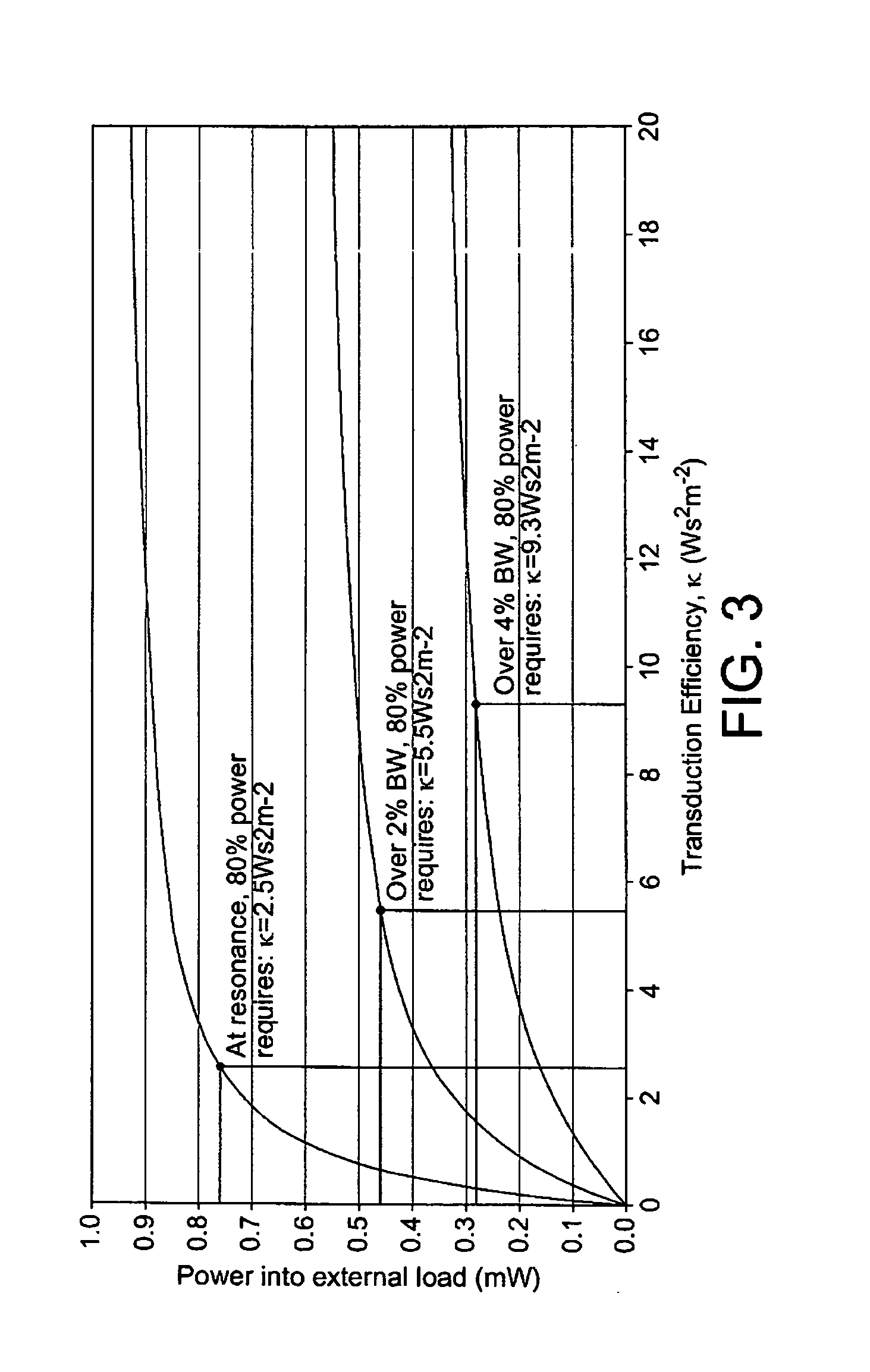
The two main problems of known electromechanical generators are that they produce too little electrical power output and have too narrow an operating bandwidth.
Power output can be improved by increasing the moving mass within the device, but bandwidth can only be improved by increasing the electromagnetic coupling.
This laboratory based model would have no utility for practical applications in the field because it would not be sufficient robust and would be, unlike the use of a cantilever beam, subject to interference by lateral vibration.
This device suffers from the problem that very high amplitude of vibration, is required to obtain useful power output; 250 micron vibration amplitude at 100 Hz which equates to around 10 g of acceleration amplitude (where g is the acceleration due to gravity).
Also, the fabrication of the micro-machined spiral spring is difficult and expensive and the paper concludes that if a spring could be designed to vibrate in a horizontal plane with rotation, rather than to vibrate in a vertical direction relative to the coil, the voltage output could be increased and the stress on the spring could be reduced.
While these prior disclosures all produce a useful mechanism for designing a theoretical electromechanical generator, when an electromechanical generator is used in a practical application, it is not possible accurately to predict the natural frequency or the optimal damping factor.
However, there is no guarantee that the practical operating conditions correspond to the theoretical ideal used to set up the electromechanical generator for the specific application.
However, it is very unlikely that the actual power output is optimized for the specific application.
Consequently, the electromechanical generator would not operate at maximum efficiency of the conversion of mechanical vibration energy into electrical energy, and thereby into useful electrical power.
Also, the frequency of ambient vibration may change during operation.
The known electromechanical generator may not be able to operate at maximum efficiency as a result of such a change.
These variables are not all predictable from the actual conditions encountered when the electromechanical generator is put into use in the field to harvest energy from a vibrating body.
The amplitude of vibration of the sprung mass may vary with time, in an intermittent and unpredictable manner.

Method used


Image

  • Electromechanical generator for converting mechanical vibrational energy into electrical energy
  • Electromechanical generator for converting mechanical vibrational energy into electrical energy
  • Electromechanical generator for converting mechanical vibrational energy into electrical energy

Examples


Embodiment Construction

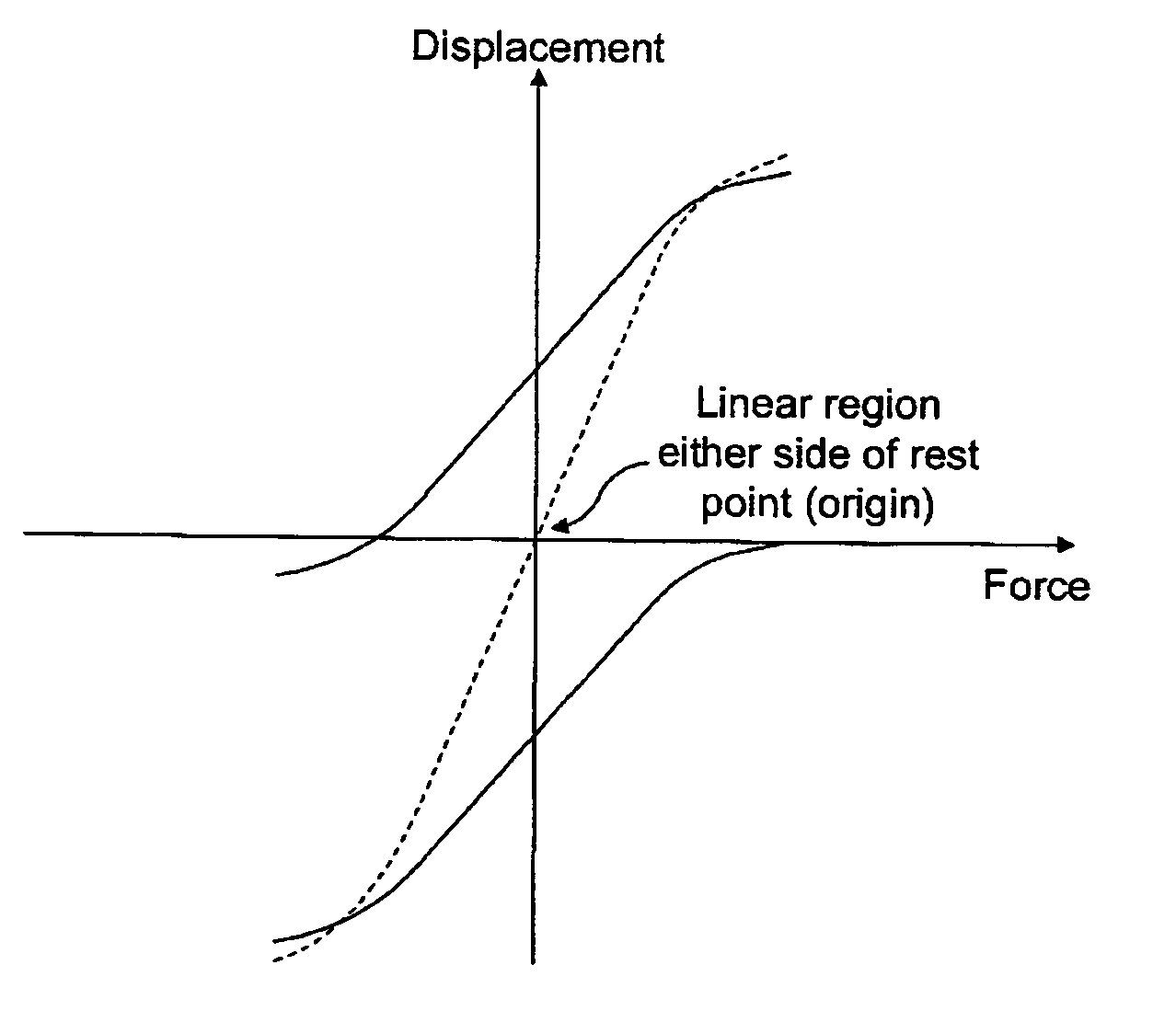
[0069] The electromechanical generator of the present invention is a resonant generator known in the art as “velocity-damped” where all of the work done by the movement of the inertial mass relative to the housing is proportional to the instantaneous velocity of that movement. Inevitably, a portion of that work is absorbed overcoming unwanted mechanical or electrical losses, but the remainder of the work may be used to generate an electrical current via a suitable transduction mechanism, such as the electrical coil / magnetic assembly described below.

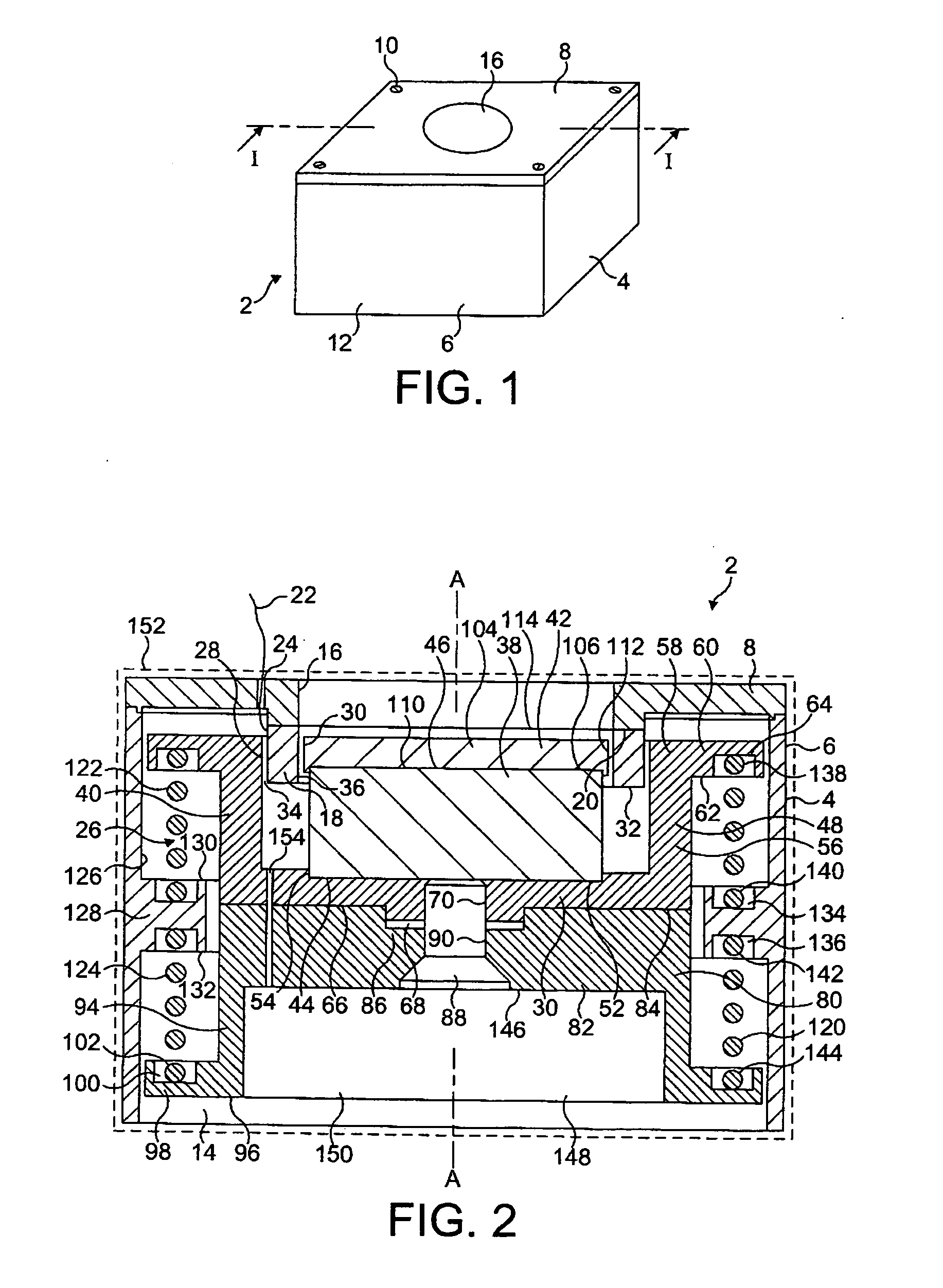
[0070]FIGS. 1 and 2 show an electromechanical generator 2 for converting mechanical vibrational energy into electrical energy in accordance with an embodiment of the present invention. 1. The electromechanical generator 2 comprises a housing 4. The housing 4 comprises an outer peripheral wall 6 and a lid 8 which is securely fitted, at corners of the lid 8, to the outer peripheral wall 6 by means of threaded bolts 10. The lid 8 is square ...


PUM


Abstract

An electromechanical generator comprising an electromechanical device for converting mechanical vibrational energy into electrical energy, the electromechanical device comprising a housing, an electrically conductive coil fixedly mounted in the housing, a magnet assembly movably mounted in the housing for linear vibrational motion along an axis, the magnet assembly having a pair of opposed polar surfaces defining a gap therebetween, the coil being disposed in the gap, and a biasing device mounted between the housing and the magnet assembly, the biasing device biasing the magnet assembly in opposed directions along the axis towards a central position.

Description

BACKGROUND TO THE INVENTION [0001] 1. Technical Field [0002] The present invention relates to an electromechanical generator for converting mechanical vibrational energy into electrical energy. In particular, the present invention relates to such a device which is a miniature generator capable of converting ambient vibration energy into electrical energy for use, for example, in powering intelligent sensor systems. Such a system can be used in many areas where there is an economical or operational advantage in the elimination of power cables or batteries. [0003] 2. Description of the Prior Art [0004] There is currently an increasing level of research activity in the area of alternative power sources for wireless sensors, such devices being described in the art as being used for ‘energy harvesting’. [0005] It is known to use an electromechanical generator for harvesting useful electrical power from ambient vibrations. A typical magnet-coil generator consists of a spring-mass combinat...

Claims


Application Information

Patent Timeline
IPC IPC(8): H02K7/18H02K35/00
CPCH02K35/02H02K35/04H02K5/136H02K7/02
Inventor ROBERTS, STEPHEN
Owner HITACHI RAIL LTD
Learn More