
Manual CNC programming system and technique to use computer aided design systems to determine cutter location information

Active Publication Date: 2007-08-16
SULLIVAN DOUGLAS G
View PDF29 Cites 56 Cited by
  • Summary
  • Abstract
  • Description
  • Claims
  • Application Information

AI Technical Summary

Benefits of technology

[0062] It is a further object of the present invention to provide a process which may be carried out relatively simply.

Problems solved by technology

Shortly after the development of computer controlled machining in the late 1940's, it became evident that a computer could control the X, Y, and Z axes of a machine, but calculating the cutter location to be entered into the computer controller to cut the parts was difficult.
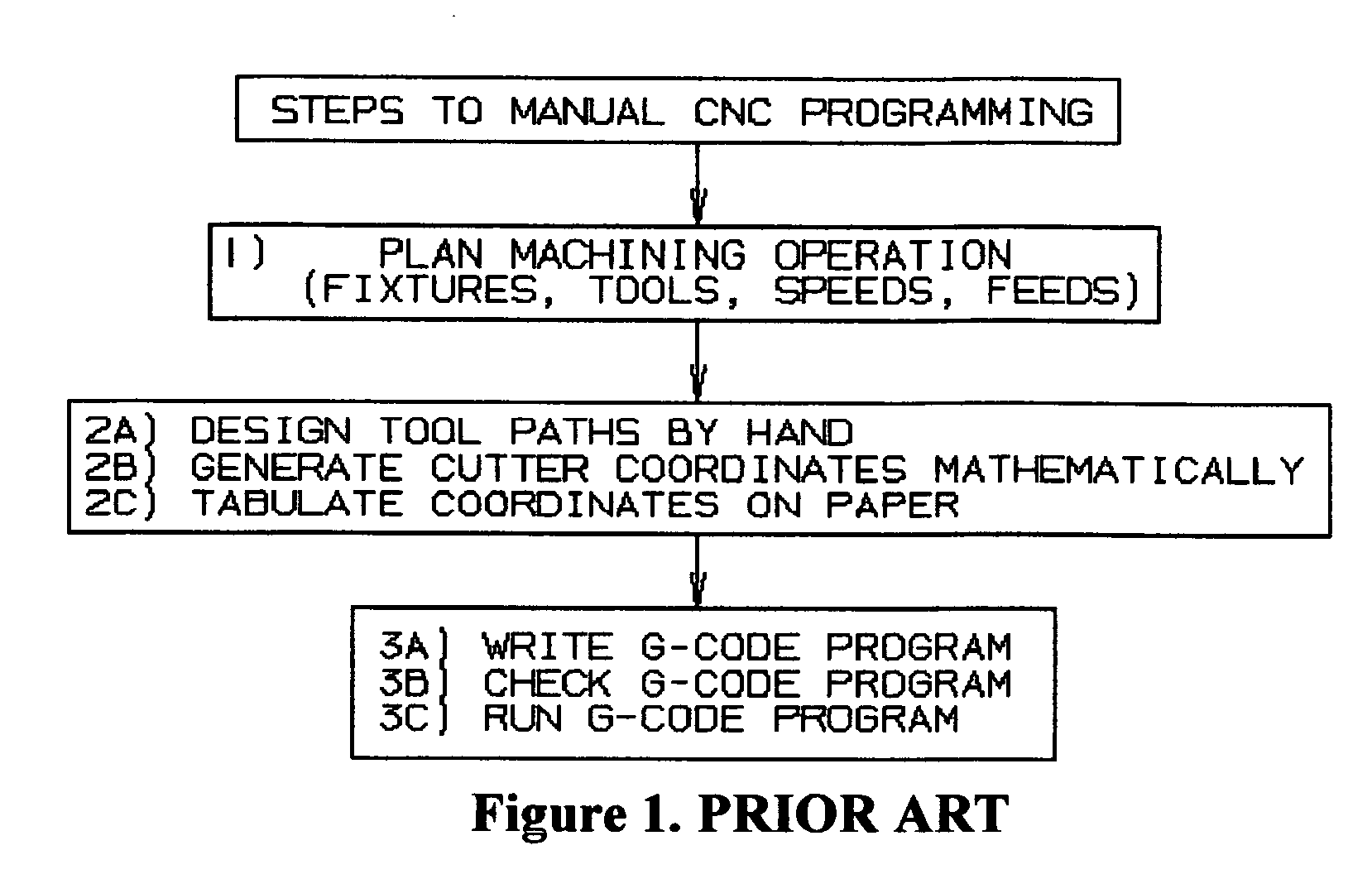
The predominant problem with Manual NC programming is the determination of cutter location information.
The two greatest drawbacks in the use of mathematics are the time necessary to do the calculations and the possibility for error.
As more complex geometry is required to be machined, the calculations take more time with greater possibility of error.
The greatest problem with APT is that it is a convoluted, difficult, high-end programming language that most machinists, NC programmers, and manufacturing engineers do not understand.
The problems with CAM systems are that they are expensive, cumbersome, and require a level of knowledge and consistency of usage that is beyond that of typical machine tool operators.
This task takes time with the potential for error.
The problem with this technique is that, typically, the features that make up the part design are not created in the sequence required in the machining operation.
The fundamental problem with developing NC programs is a matter of determining the cutter location information, i.e., the X, Y, and Z coordinates.
Those skilled in the art of manual CNC programming know that manual CNC programming is tedious, error prone, and math intensive.
Those skilled in the art know that in addition to the time and difficulty associated with the math requirements to generate cutter coordinates, there are other problems associated with manual CNC programming.
The amount of time and errors associated with manually writing and checking the CNC program are well known.
Although calculators and text editors are very beneficial, especially when compared to the alternatives, there are voids in the technology that, if made available, could alleviate much of the time and errors that are associated with manual CNC programming.
The missing technologies specifically include the lack of a means to perform a graphical verification of the tool path created by the manually generated cutter coordinates, the lack of a means to modify (copy, move program zero, etc.) the manually generated cutter coordinates, and most significantly a lack of a means to manually generate cutter coordinates with Computer Aided Design (CAD) technologies available that would be much easier, faster and more accurate than through the mathematical approach previously discussed herein.

Method used


Image

  • Manual CNC programming system and technique to use computer aided design systems to determine cutter location information
  • Manual CNC programming system and technique to use computer aided design systems to determine cutter location information
  • Manual CNC programming system and technique to use computer aided design systems to determine cutter location information

Examples


Embodiment Construction

[0084] For a further understanding of the nature, function, and objects of the present invention, reference should now be made to the following detailed description taken in conjunction with the accompanying drawings. Detailed descriptions of the preferred embodiments are provided herein, as well as, the best mode of carrying out and employing the present invention. It is to be understood, however, that the present invention may be embodied in various forms. Therefore, specific details disclosed herein are not to be interpreted as limiting, but rather as a basis for the claims and as a representative basis for teaching one skilled in the art to employ the present invention in virtually any appropriately detailed system, structure, manner, or environment. The practice of the present invention is illustrated by the following examples which are deemed illustrative of the process taught by the present invention as well as providing the teachings for the products and articles of manufact...


PUM


Abstract

A manual computer numerical control (CNC) programming method and system (which may be embodied in whole or part in an article of manufacture or apparatus) in which coordinates may be manually entered into a text editor into a file format known as the coordinate work sheet (CWS) including verification, modification and conversion of the CWS to G-Code, the coordinate work sheet format being a comma delimited ASCII text file, and further including cutter on / off commands and using computer aided design (CAD) data to generate the coordinate work sheet (CWS).

Description

BACKGROUND OF THE INVENTION [0001] 1. Field of the Invention [0002] The present invention relates generally to numerical control of machines and more specifically and particularly to a new and improved method and apparatus for the manual CNC programming of numerical control machines and for such other structures and methods as may be herein disclosed. [0003] 2. Background Information [0004] Shortly after the development of computer controlled machining in the late 1940's, it became evident that a computer could control the X, Y, and Z axes of a machine, but calculating the cutter location to be entered into the computer controller to cut the parts was difficult. [0005] Many computer controlled machines are programmed using the NC programming language (EIA-274) which is comprised of straight-forward commands. As used herein EIA-274, G-Code and Word Address Programming are synonymous. [0006] The techniques available for writing NC programs include Manual Programming, Conversational Pr...

Claims


Application Information

Patent Timeline
IPC IPC(8): G05B19/42
CPCG05B19/4093Y02P90/02
Inventor SULLIVAN, DOUGLAS G.
Owner SULLIVAN DOUGLAS G
Learn More