
Free fall detector device and free fall detection method

a detector device and detector technology, applied in the direction of acceleration measurement in multiple dimensions, acceleration measurement using interia forces, devices characerised by mechanical means, etc., can solve the problems of conflict or slowing down of operations, the surface of the disk and the read/write head is practically in contact, and the use is very delicate,

Active Publication Date: 2007-08-16
STMICROELECTRONICS SRL
View PDF4 Cites 9 Cited by
  • Summary
  • Abstract
  • Description
  • Claims
  • Application Information

AI Technical Summary

Benefits of technology

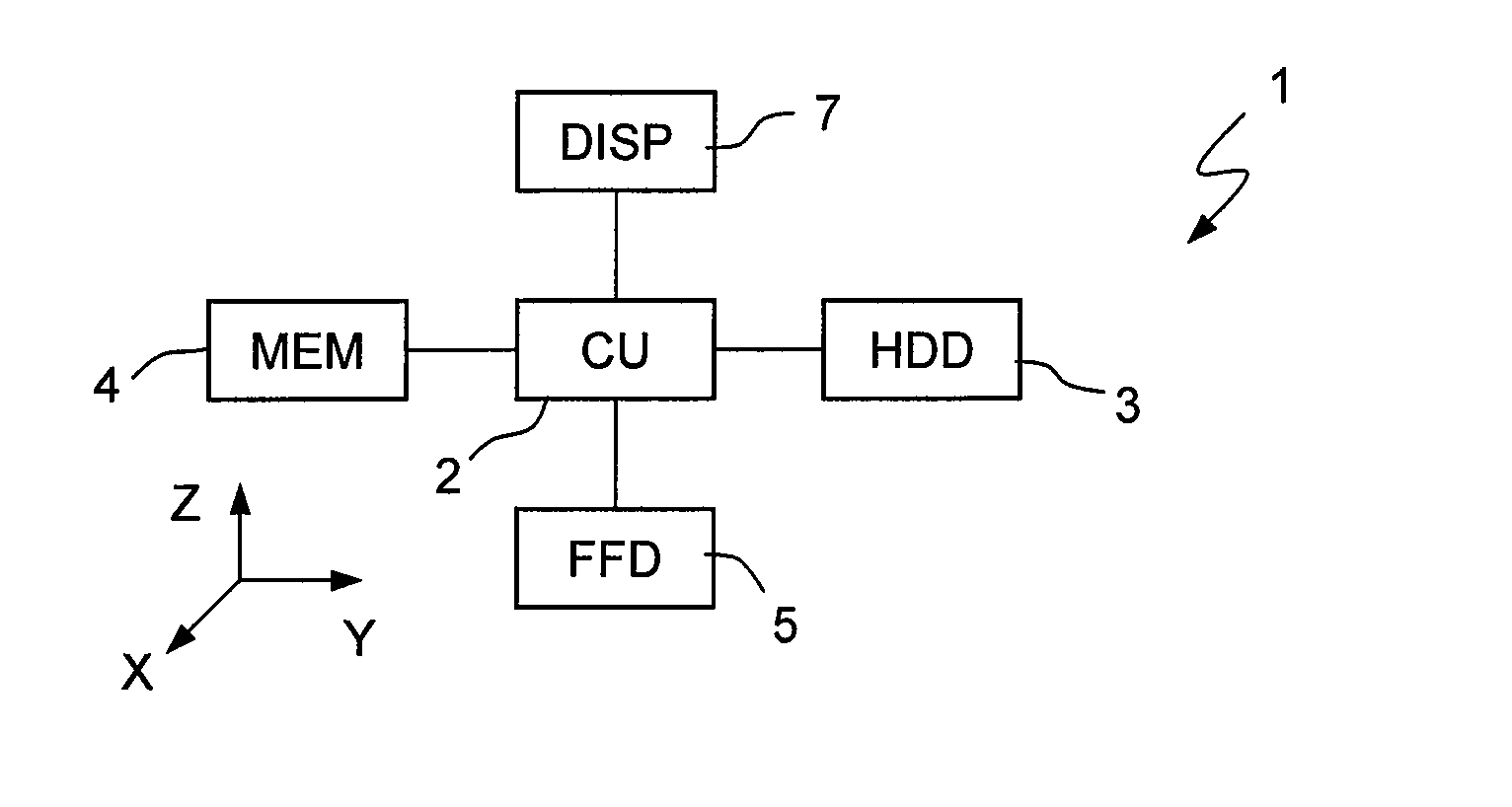
[0012] One embodiment of the present invention is a free-fall detector device and a free-fall detection method, which enables the drawbacks described to be overcome.

Problems solved by technology

Owing to the increasingly marked miniaturization, for example, many of the devices listed above are equipped with hard disks, which call for an extremely high mechanical precision and have very delicate parts.
The surfaces of the disks and the read / write heads, in use, are practically in contact and can be seriously damaged as a result of impact caused by a fall.
Consequently, conflicts or slowing-down of operations may occur if the processing unit is shared with the device that incorporates the free-fall detector.
To prevent conflicts and slowing-down, it is necessary to provide an independent processing unit, which, however, entails a considerable waste of space.

Method used


Image

  • Free fall detector device and free fall detection method
  • Free fall detector device and free fall detection method
  • Free fall detector device and free fall detection method

Examples


second embodiment

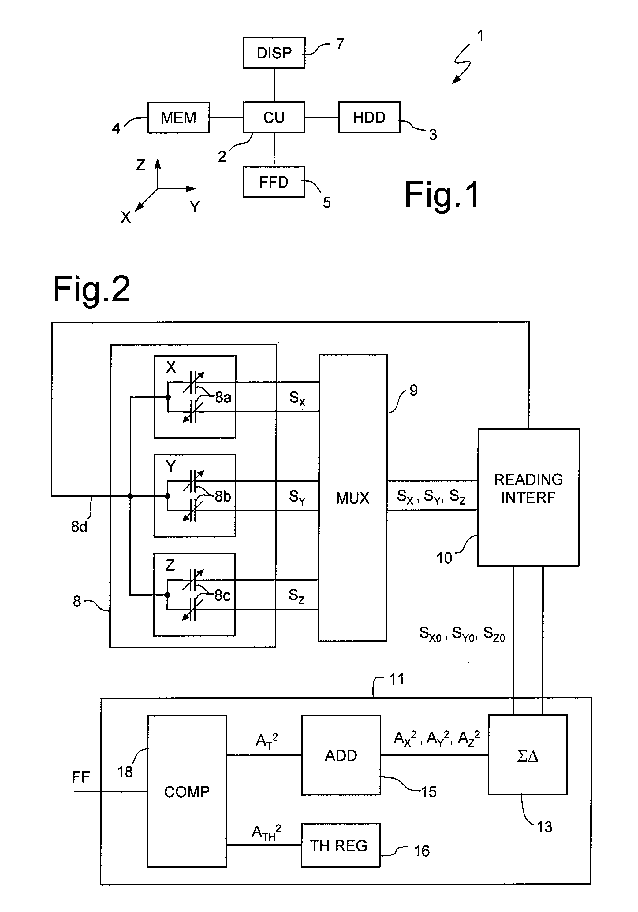
[0054]FIG. 6, in which parts that are the same as those already illustrated are designated by the same reference numbers, shows the invention. In this case, a free-fall detector 100 comprises the inertial sensor 8, the reading interface 10, and a fully analog processing stage 111. In greater detail, the processing stage 111 comprises a demultiplexer 112, a first memory capacitor 115a, a second memory capacitor 115b, and a third memory capacitor 155c, a comparator 120 and a reference line 125 supplying a reference threshold signal STHR. The first, second, and third memory capacitors 115a, 115b, 115c are selectively and sequentially connectable to the outputs 10a, 10b of the reading interface 10 by the demultiplexer 112 for receiving, respectively, the first, second and third detection signals SXO, SYO, SZO, which are proportional to the square of the moduli of the acceleration components detected by the inertial sensor 8 according to the first, second, and third detection axes X, Y, ...

third embodiment

[0058]FIGS. 7 and 8, in which parts already illustrated are again designated by the same reference numbers, show the invention.

[0059] In this case, a free-fall detector 200 comprises an inertial sensor 208, a multiplexer 209, a reading interface 210, and the processing stage 11.

[0060] The inertial sensor 208 is again a linear accelerometer of a capacitive MEMS type with mutually perpendicular and independent first, second, and third detection axes X, Y, Z. In FIG. 7, the inertial sensor 208 is represented schematically by a first, second, and third pair of capacitors 208a, 208b, 208c having variable capacitance in response to forces and accelerations acting on the inertial sensor 8 according to the first, second, and third detection axes X, Y, Z, respectively.

[0061] In this case, each pair of capacitors 208a, 208b, 208c has a terminal in common, connected to a detection terminal 208d of the inertial sensor 8, and two driving terminals, selectively and sequentially connectable to d...


PUM


Abstract

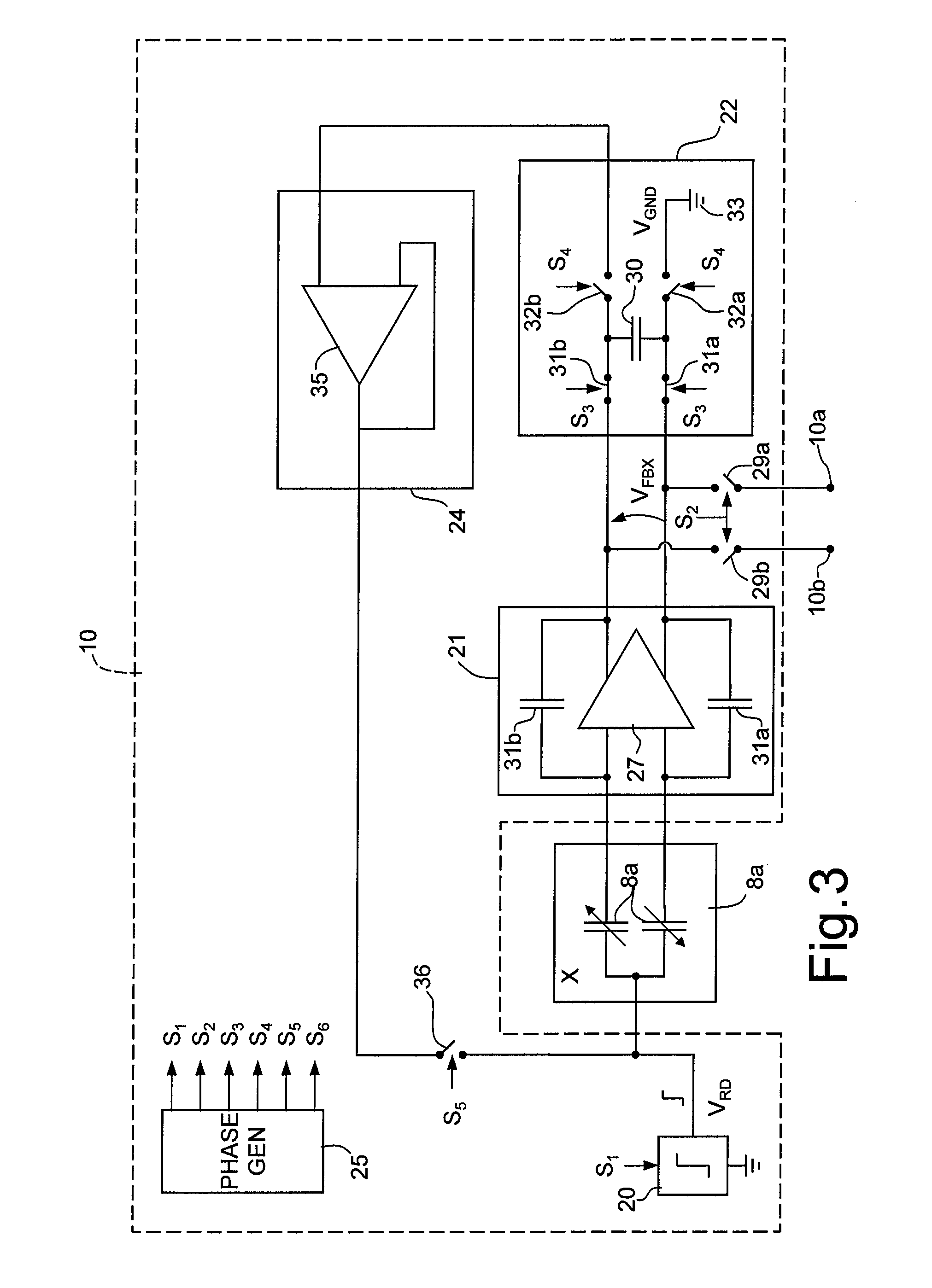
A free-fall detector device includes an inertial sensor, a detection circuit associated to the inertial sensor, and a signal source for supplying a read signal to the inertial sensor. The device moreover includes: a storage element, selectively connectable to the detection circuit for storing a feedback signal generated by the detection circuit in response to the read signal supplied to the inertial sensor; and a feedback circuit coupled to the storage element for supplying the feedback signal to the inertial sensor so that the detection circuit generates at least one detection signal in response to the feedback signal supplied to the inertial sensor.

Description

BACKGROUND OF THE INVENTION [0001] 1. Field of the Invention [0002] The present invention relates to a free-fall detector device for and to a free-fall detection method. [0003] 2. Description of the Related Art [0004] As is known, the use of microelectromechanical or MEMS (Micro-Electro-Mechanical-Systems) inertial sensors is becoming increasingly common for different reasons in a wide range of portable electronic devices, such as cell phones, laptops and palmtops, camcorders, digital cameras, and the like. In these devices, in particular, the inertial sensors are often advantageously exploited for making free-fall detectors, which enable prevention or at least reduction of the damage deriving from impact by bringing sensitive parts into a safety configuration. Owing to the increasingly marked miniaturization, for example, many of the devices listed above are equipped with hard disks, which call for an extremely high mechanical precision and have very delicate parts. The surfaces of...

Claims


Application Information

Patent Timeline
IPC IPC(8): H01H47/00G01P15/18
CPCG01P15/0891G01P15/125G11B21/12G01P15/18G11B19/043G01P15/131
Inventor LASALANDRA, ERNESTOUNGARETTI, TOMMASO
Owner STMICROELECTRONICS SRL
Learn More