
Broadband polarized antenna including magnetodielectric material, isoimpedance loading, and associated methods

a polarized antenna and magnetodielectric material technology, applied in the field of communications, can solve the problems of not being able to reduce the size of the antenna, reducing radiation bandwidth and gain, and not being able to control the expansion of the wave, etc., and achieve the effect of increasing bandwidth and not being limited in bandwidth

Active Publication Date: 2007-08-16
HARRIS CORP
View PDF11 Cites 53 Cited by
  • Summary
  • Abstract
  • Description
  • Claims
  • Application Information

AI Technical Summary

Benefits of technology

"The present invention provides a small omnidirectional antenna with increased bandwidth. It uses a circularly or rotationally polarized antenna element and an isoimpedance magnetodielectric layer. The magnetodielectric layer is made of a high Curie temperature nickel zinc ferrite or a mixture of magnetic and dielectric materials. The layer can also include glass microspheres or foam. The method involves making an antenna by surrounding the antenna element with the magnetodielectric layer. The technical effects of this invention include increased bandwidth, a broadband loading approach for antenna miniaturization, and a broadband radome and shell which is not limited in bandwidth."

Problems solved by technology

Unfortunately, antennas have not been reduced in size at a comparative level and often are one of the larger components used in a smaller communications device.
In this loading, dielectric loading effects are nominal, and controlled wave expansion is not an objective.
Unfortunately, resistive loading decreases radiation bandwidth and gain.
They can be bandwidth limiting, unless they are electrically thin in structure.
Thin radomes have more bandwidth, but may be mechanically weak.
Unfortunately however, it is narrow in bandwidth.

Method used


Image

  • Broadband polarized antenna including magnetodielectric material, isoimpedance loading, and associated methods
  • Broadband polarized antenna including magnetodielectric material, isoimpedance loading, and associated methods
  • Broadband polarized antenna including magnetodielectric material, isoimpedance loading, and associated methods

Examples


Embodiment Construction

[0022] The present invention will now be described more fully hereinafter with reference to the accompanying drawings, in which preferred embodiments of the invention are shown. This invention may, however, be embodied in many different forms and should not be construed as limited to the embodiments set forth herein. Rather, these embodiments are provided so that this disclosure will be thorough and complete, and will fully convey the scope of the invention to those skilled in the art. Like numbers refer to like elements throughout.

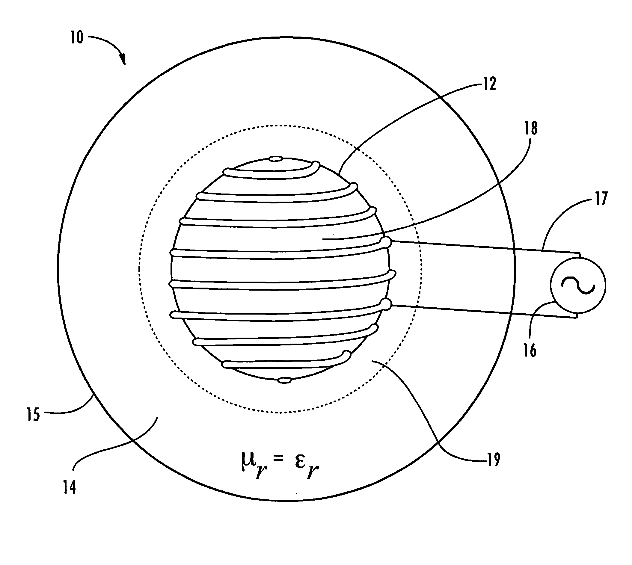
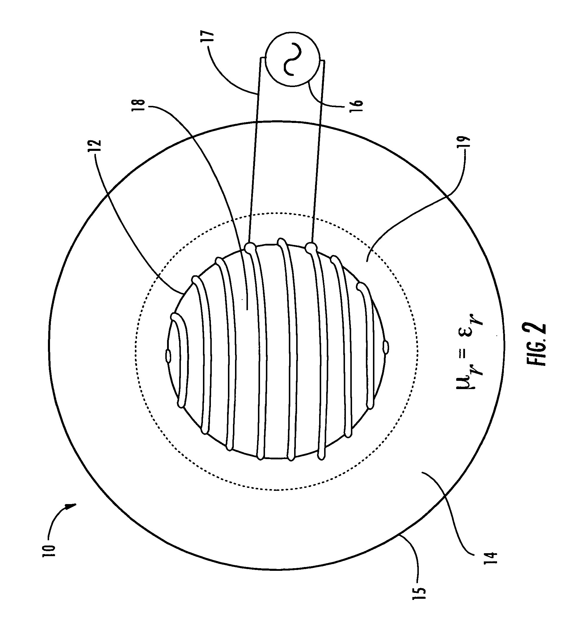
[0023] Referring to FIG. 1, a small circularly polarized omnidirectional antenna 10 with increased bandwidth will now be described. The antenna 10 may be included, for example, in a mobile communications device 20. Such a mobile communications device may be a handheld radio, cell phone or wireless email device including a portable housing 22, a battery (not shown) carried by the portable housing, a transceiver 24 and processor 26 connected to the antenna...


PUM


Abstract

The broadband small antenna has equal magnetic electric proportions, circular polarization, and an isoimpedance magnetodielectric (μr≡εr) shell for controlled wave expansion. The shell is a radome without bandwidth limitation, with reflectionless boundary conditions to free space, providing loading and broad bandwidth antenna size miniaturization. The system is spherically structured based upon size, quality (Q) and bandwidth.

Description

FIELD OF THE INVENTION [0001] The present invention relates to the field of communications, and more particularly, to antennas, and related methods. BACKGROUND OF THE INVENTION [0002] In antennas, size dictates bandwidth because field expansion occurs at a finite rate, given by the speed of light. This gives rise to the well known size-bandwidth limitation known as Chu's limit (CHU, L. J.: “Physical Limitations In Omnidireactional Antennas”, J Appl. Phys, 1948, 19, pp. 1163-1175). [0003] Newer designs and manufacturing techniques have driven electronic components to small dimensions and miniaturized many communication devices and systems. Unfortunately, antennas have not been reduced in size at a comparative level and often are one of the larger components used in a smaller communications device. To reduce antenna size, relative to free space wavelength, loading is typically used. Loading may take various forms, including, circuit loading and material loading. [0004] In dielectric m...

Claims


Application Information

Patent Timeline
Patent Type & Authority Applications(United States)
IPC IPC(8): H01Q7/08
CPCH01Q1/243H01Q3/446H01Q1/42H01Q1/362
Inventor PARSCHE, FRANCIS EUGENE
Owner HARRIS CORP
Learn More