Multi-chamber mixing ampoule

a multi-chamber, ampoule technology, applied in the field of medical ampoules, can solve the problems of complex design and manufacture of barked devices, not being well suited for medical applications, and not being able to dispense combined components, etc., and achieve the effect of simple design

Inactive Publication Date: 2007-08-09
HAIMI SHLOMO +1
View PDF3 Cites 22 Cited by
  • Summary
  • Abstract
  • Description
  • Claims
  • Application Information

AI Technical Summary

Benefits of technology

[0006] The present invention is a multi-chambered ampoule configured to allow mixing of two

Problems solved by technology

The Barked device suffers from complexity of design and manufacture and does not allow for dispensing of the combined components into a standard syringe or with another dispensing device.
T

Method used


Image

  • Multi-chamber mixing ampoule
  • Multi-chamber mixing ampoule
  • Multi-chamber mixing ampoule

Examples


embodiment 2

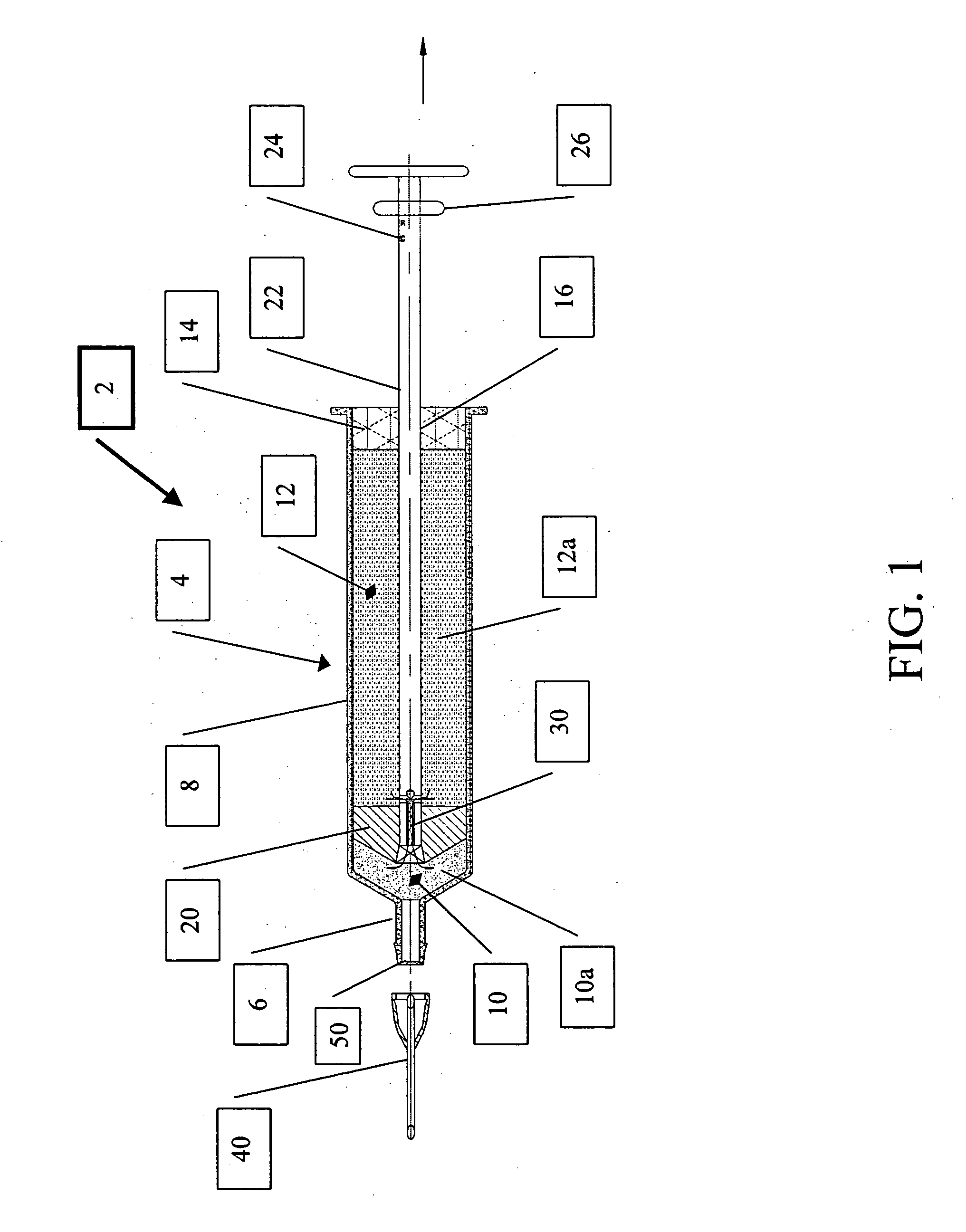
[0042] Referring now to the drawings, FIGS. 1-4 illustrate a first preferred embodiment 2 that may be used primarily as a syringe. The syringe housing 4 is configured with a proximal dispensing end 6 and a substantially cylindrical body 8. The proximal dispensing end 6 may be sealed by a removable cap or, as illustrated here, an ampoule sealing membrane 50 as is known in the art. The syringe housing 4 is sealed at its distal end by an end plug 14, which is configured with an axial through bore 16. The interior volume of the body 8 is divided into first 10 and second 12 storage regions by the axially displaceable piston element 20. Each of the storage regions 10 and 12 contain different components 10a and 12a respectively that are to later be combined and mixed together into the mixture referred to as 1012a. Component 12a is preferably a liquid. As mentioned above, either of the first 10 and second 12 storage regions may be sealed in a vacuum state. This may be of particular benefit ...

embodiment 200

[0049] Alternatively, the ampoule of embodiment 200 may be used with an appropriately configured injection device.

[0050] This embodiment, as illustrated in FIG. 6, may also have a needle cannula 240 attached to the distal end 206 of the ampoule housing 204 and the mixture may be delivered directly to the patient.


PUM


Abstract

The present invention provides a multi-compartment ampoule for the storage of the separated components of a multiple component mixture and then mixing them together in a single ampoule. The ampoule housing has a proximal dispensing end. The distal end of the ampoule housing is sealed by an end plug configured with an axial through bore. A portion of an axially displaceable plunger element passes thorough the axial through bore and extends into the interior volume and is fixedly attached to an axially displaceable piston element slideablely deployed within the ampoule housing so as to sealingly divide the interior volume into at least first and second storage regions that are pre-filled with the separate components that will be mixed together just prior to use. Axial displacement of the plunger element, and thereby the piston element, in a first direction discharges a first component of the mixture from the distal storage region through a one-way flow configuration into the proximal storage region. After the two components are in a single storage region, they may be thoroughly mixed together. Once the components are mixed, dispensing of the mixture may be by any number of methods. The mixture may be dispensed as if from a standard ampoule, wherein the needle of a syringe is inserted through the sealing membrane and the prescribed amount of the mixture is drawn out. Alternatively, the ampoule may be inserted into an injection device, such as an injection pen for example, in a manner similar to a standard ampoule. The additional features of a needle cannula configured for attachment directly to the proximal dispensing end of the ampoule housing and graduated markings on the shaft of the plunger that are indicative of volume dispensation combined with the basic ampoule provides an embodiment that can store the separated components of the mixture before use, provide a way of mixing the components together in the same ampoule and that can be used as the syringe to dispense the mixture directly into the patient.

Description

FIELD AND BACKGROUND OF THE INVENTION [0001] The present invention relates to medical ampoules and, in particular, it concerns a multi-chambered ampoule configured to allow mixing of two or more substances just prior to use. [0002] It is known to provide medical storage containers having multiple compartments in which the seal between the compartments is breached and the contents of the compartments are mixed just prior to use. These storage containers are particularly useful with medications whose unmixed shelf life is longer than its mixed shelf life. Some of these containers employ a method of puncturing or tearing a sealing membrane. [0003] U.S. Pat. No. 6,981,963 to Barker et al. discloses a device for mixing and injecting medication from a two-chambered cartridge. A two-chambered cartridge is attached to a barrel and contains components of a medication stored separately in the chambers. A plunger in the rearward end of the cartridge can be advanced into the cartridge thereby f...

Claims


Application Information

Patent Timeline
IPC IPC(8): A61M37/00
CPCA61M5/31596A61M5/284
Inventor HAIMI, SHLOMOMENASHE, YEHEZKEL
Owner HAIMI SHLOMO
Why Eureka
Try Eureka