Pin assembly for conveyor chain

a conveyor chain and pin assembly technology, applied in the direction of driving chains, coupling device connections, conveyors, etc., can solve the problems of rough surface, inability to form in the manner, and less desirable and less suitable for some chain applications, so as to reduce surface irregularities, facilitate formation, and smooth pin surface

Inactive Publication Date: 2007-08-09
FROST TECH
View PDF56 Cites 5 Cited by
  • Summary
  • Abstract
  • Description
  • Claims
  • Application Information

AI Technical Summary

Benefits of technology

[0006] The present invention provides a pin assembly that has a pin element formed with a pin head or head portion at one end of a shaft portion and an attachment portion at the other end of the shaft portion. An attachment, such as a second pin head portion or a side link / pusher member or the like, is formed separately and is attached to the attachment portion to define the opposite end of the pin element (and optionally with an extension extending past the second head portion for mounting an accessory or object to the pin element). Because the pin element is formed without one of the heads of the pin, the pin element may be readily formed by a cold-forming process or other process that results in an exterior surface that has reduced surface irregularities to provide a substantially smooth pin surface (as compared to a roughened surface of a forged pin).
[0013] Therefore, the present invention provides a pin assembly with an attachment portion at an end of the shaft of the pin element. The separately formed attachment or head portion may be attached to the attachment portion of the pin element. For example, a second head portion may be attached to the attachment portion to form an I-pin, while an extension may extend through the second head portion and may provide a mounting element (such as a threaded end of the pin) for attaching an object or accessory to the pin assembly. Optionally, a side link and pusher member may be attached to the attachment portion to assemble the side link to the pin element. The pin element and / or attachment may have substantially smooth surfaces as compared to forged pins, such as may be achieved by cold forming of the pin element separate from the attachment (which may also be cold-formed or otherwise formed via a separate forming process from that of the pin element). The two-piece construction of the pin assembly of the present invention thus allows the pin assembly to be formed with substantially smooth components and structurally enhanced components as compared to conventional forgings.

Problems solved by technology

Because such pins have a threaded portion extending past the head of the pin, they cannot be formed in the manner of the smooth link pins and the like.
Rather, such pins must be forged as a unitary pin to achieve the desired form, and thus have a roughened surface and are less desirable and less suitable for some chain applications.

Method used


Image

  • Pin assembly for conveyor chain
  • Pin assembly for conveyor chain
  • Pin assembly for conveyor chain

Examples


Embodiment Construction

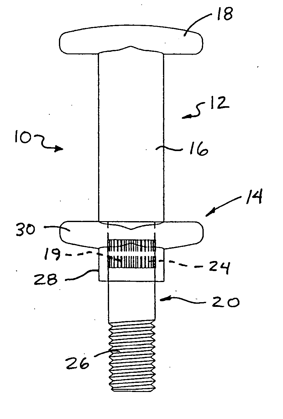
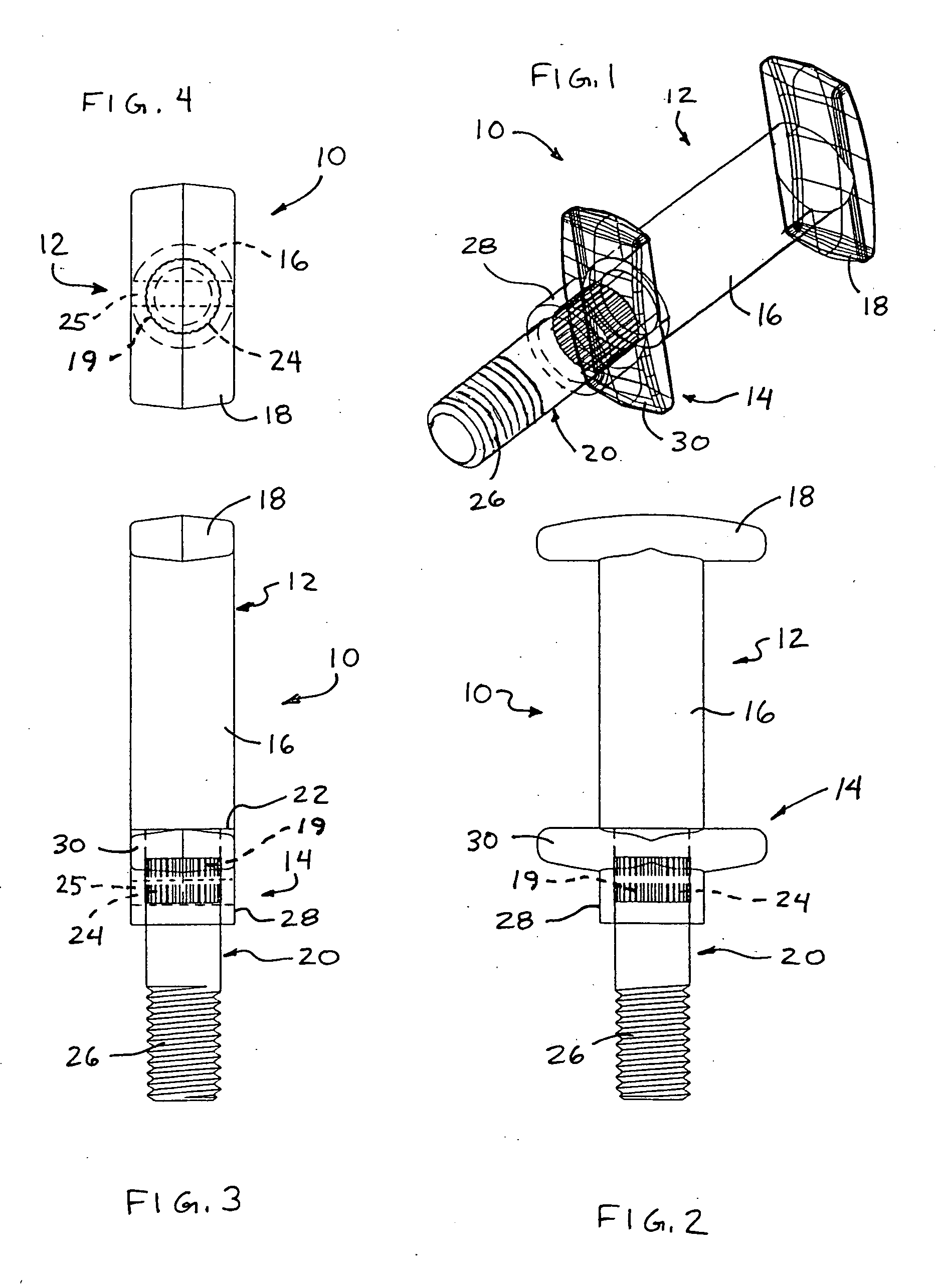
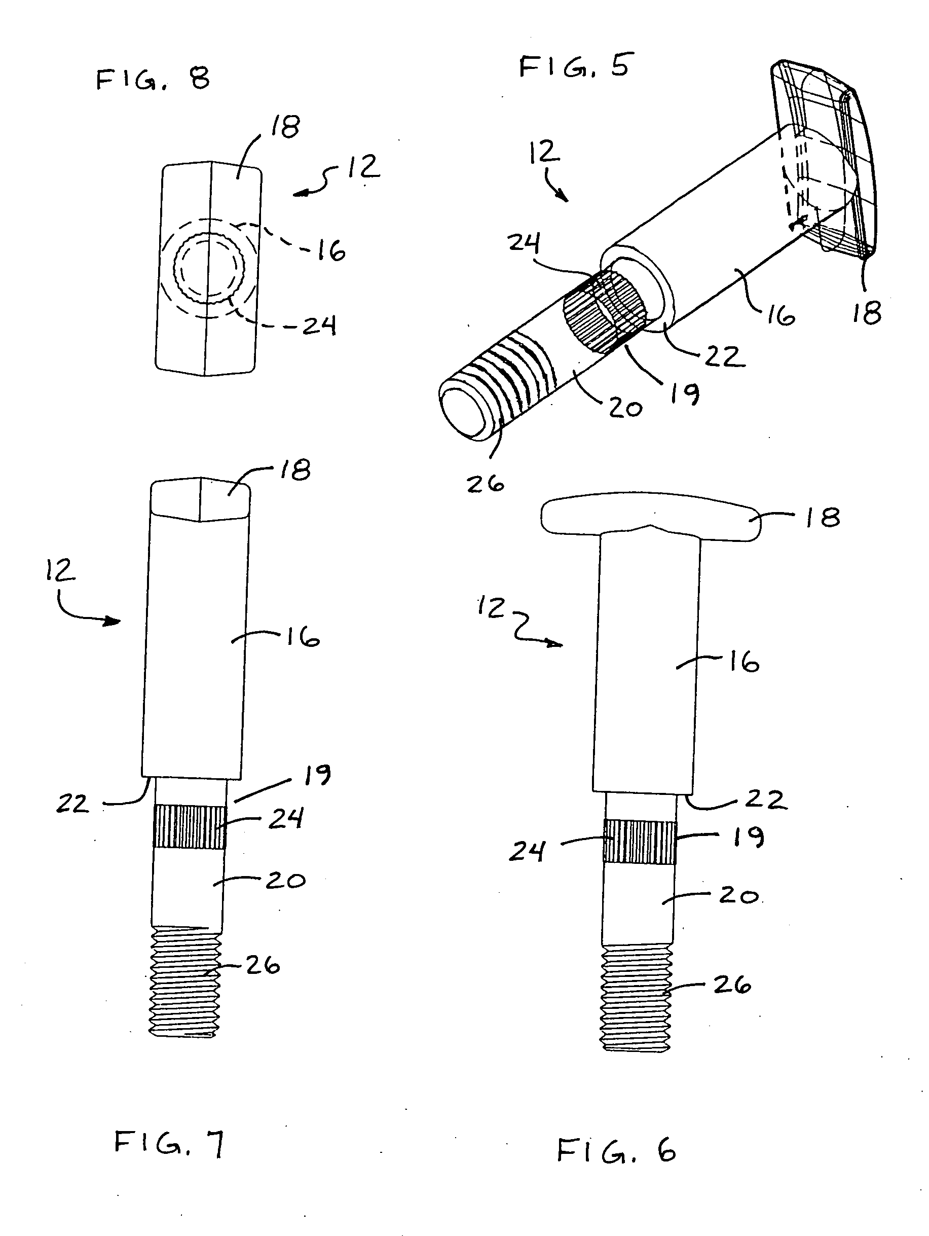
[0037] Referring now to the drawings and the illustrative embodiments depicted therein, a pin assembly 10 for a chain or section of chain for conveying product along a conveying system, such as for material handling or processing systems or the like, includes a pin body or body portion or pin element 12 and an attachment or attachment element, such as a head portion or element 14 (FIGS. 1-12). Pin element 12 includes a shaft portion 16, a pin head or head element or portion 18 at an end of the shaft portion 16, and an attachment portion 19 at the other end of the shaft portion. Pin element 12 also includes an extension or extension member or portion 20 extending from the attachment portion 19 at the end of the shaft portion 16. Pin element 12 is formed separately from head element 14, and head element 14 is positioned on pin element 12 to assemble the pin assembly 10, as discussed below. Pin element 12 and / or head element 14 may be formed to have reduced surface irregularities, such...


PUM

PropertyMeasurementUnit
diameteraaaaaaaaaa
surface irregularitiesaaaaaaaaaa
shapeaaaaaaaaaa

Abstract

A pin assembly for a chain of a material handling system includes a pin element and an attachment element. The pin element includes a shaft portion, a head portion at an end of the shaft portion, and an attachment portion at an end of the shaft portion opposite the head portion. The attachment element is configured to attach to the attachment portion of the pin element, and is positionable at the attachment portion and is retainable thereto. The attachment element may comprise a second head portion to define an I-type pin assembly or may comprise a side link and pusher member construction or other element or member. A mounting extension may extend from the attachment portion for mounting an object to the pin assembly after the attachment is attached to the pin element.

Description

CROSS REFERENCE TO RELATED APPLICATION [0001] The present application claims the benefit of U.S. provisional application, Ser. No. 60 / 739,587, filed Nov. 23, 2005, which is hereby incorporated herein by reference in its entirety.FIELD OF THE INVENTION [0002] The present invention relates generally to chains for a conveying system and, more particularly, to pins for chains and conveying systems that require at least some of the pins to mount or attach an object at one of the ends of the pin. BACKGROUND OF THE INVENTION [0003] Chains for power transmission or for material handling and processing systems, such as, for example, chains which function to move a plurality of trolleys or the like along a path in a processing plant, warehouse or the like, typically include multiple sections or links joined together by pins or bolts, such as I-pins. The links typically include a center link connected at each end to a pair of side links by a pin, such that the links move or pivot relative to o...

Claims


Application Information

Patent Timeline
Patent Type & Authority Applications(United States)
IPC IPC(8): H01R33/02
CPCB21K1/00B65G19/245B21L13/00
Inventor RATHBUN, JONATHAN M.SCHMIDT, WAYNE E.FROST, CHARLES C.
Owner FROST TECH
Why Eureka
Try Eureka