[0011]Besides, according to a prior-art technique, a method for notifying a failure in the case where the failure has been detected by an access point diagnosis unit is such that the failure is notified to the maintenance center of the radio access point through a line which is connected to the radio access point by wire (refer to, for example,
Patent Document 2). In the maintenance center, a failure
recovery operation is performed on the basis of the failure information notified by the radio access point. In the case of the above notification method, it is presupposed that a line interface portion for connecting the radio access point and a network is operating normally. In a case, for example, where the line interface portion is unusable, the failure information cannot be notified. In case of considering the reliability of the system, the reliability of the wired line can be enhanced by a method such as dualizing the line interface portion, but this
countermeasure is costly. Besides, in the worst case, it is supposed that both the dual line interface portions become unusable on account of any cause, so serious evil influence might be exerted on the
continuation of
service provision. In such a case, if the failure information of the access point can be notified without using an existing wired path, the failure can be notified in
spite of the occurrence of any failure in the wired circuit, so the
recovery of the system from the failure can be quickened. Besides, when a path along which the failure information of the access point can be obtained even in a place outside the maintenance center is established, a prompt and flexible maintenance can be executed without being limited to the specified place. Moreover, the notification of the failure information to outside the maintenance center is broadcast to many persons concerned with the maintenance of the access point, whereby the failure information can be shared to, bring forth the merit that the maintenance of the access point can be made multifarious.
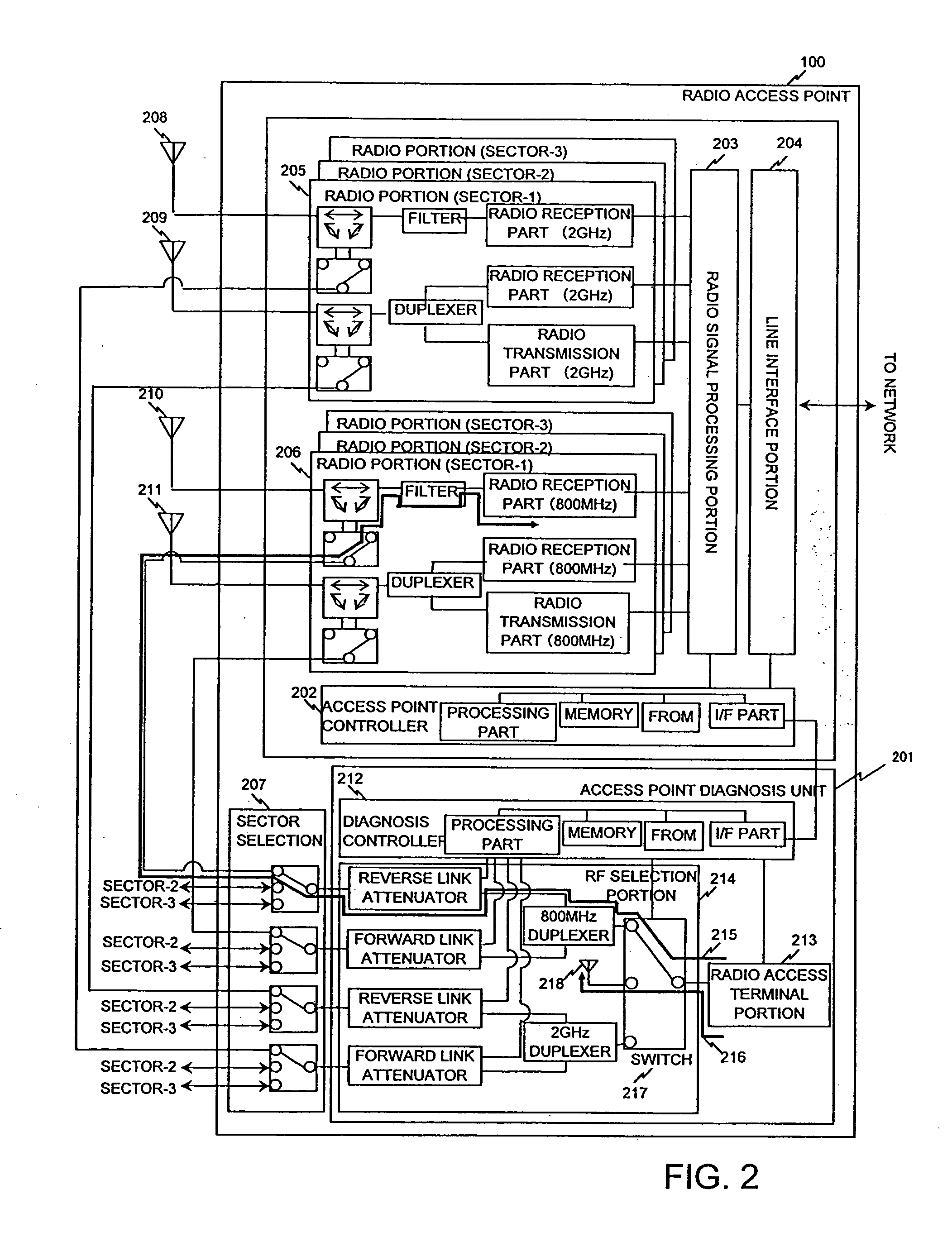
[0013]The invention has for one of its objects to realize the above notification method without altering the diagnostic method of a known radio access point, and by remodeling the configuration of the radio access point on a small scale. Another object of the invention is to make a radio access terminal portion use an SMS (
Short Message Service) which is a known technique or a known technique (refer to, for example,
Patent Document 3) in which the
International Mobile Subscriber Identity (IMSI) for use in the identification of a portable access terminal is translated into an
IP address so as to transmit an IP packet to the specified
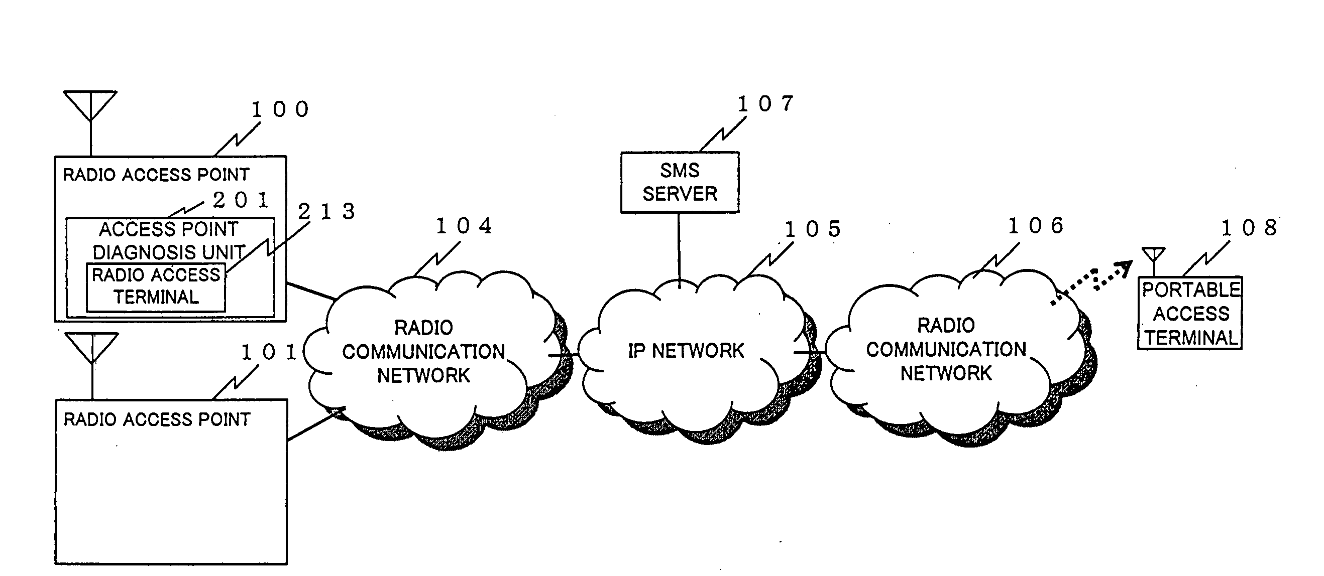
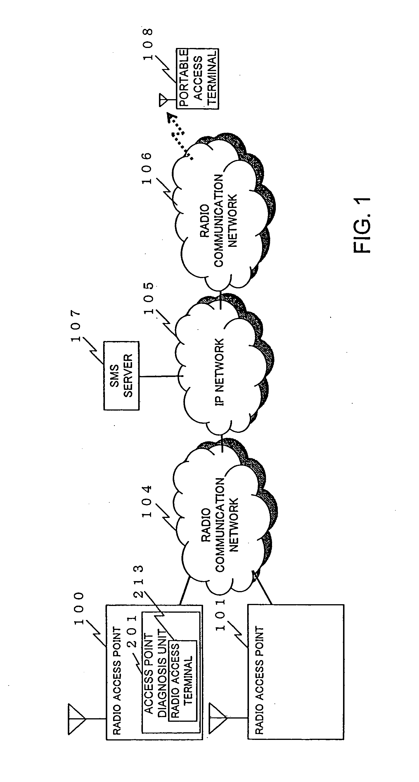
IP address, whereby the portable access terminal of a notification destination is permitted to receive the notice of the failure information of the radio access point by the existing data communication technique. Especially the SMS is the known technique in a present-day radio communication system, and has the important merit that a traffic necessary for the transmission of a message is very small.
[0014]The invention has for one of its objects to realize a maintenance operation which enhances responsiveness more flexibly, in such a way that, even in a case where the maintenance engineer of a radio access point is not present in a maintenance center as in the prior art, failure information is notified to a specified portable access terminal carried by the maintenance engineer, whereupon the maintenance engineer remotely accesses a maintenance access terminal (PC) installed in, for example, the maintenance center. Another object of the invention is to set a plurality of portable access terminals to which failure information is notified, and to expand the failure information of identical content in the portable access terminals carried by maintenance engineers, thereby to diminish artificial mistakes, for example, that the failure of the radio access point is coped with later because a certain maintenance engineer does not take note of the occurrence of the failure.
[0044]According to the invention, it is realizable to notify the result of an access point diagnosis to a specified portable access terminal other than a maintenance center. Besides, according to the invention, it is realizable to notify the failure information of an access point to the specified portable access terminal even in a case where the radio access point cannot communicate with the maintenance center on account of any failure. According to the invention, the notification method indicated above can be realized without altering the diagnostic method of a known radio access point, and by remodeling the configuration of the radio access point on a small scale. According to the invention, a radio access terminal portion uses an SMS which is a known technique or a known technique (refer to, for example,
Patent Document 3) in which the
International Mobile Subscriber Identity (IMSI) for use in the identification of a portable access terminal is translated into an
IP address so as to transmit an IP packet to the specified IP address, whereby the portable access terminal of a notification destination can realize the reception of the notice of the failure information of the radio access point by the existing data communication technique. Especially the SMS is the known technique in a present-day radio communication system, and has the important merit that a traffic necessary for the transmission of a message is very small.
[0045]According to the invention, it is possible to realize a maintenance operation which enhances responsiveness more flexibly, in such a way that, even in a case where the maintenance engineer of a radio access point is not present in a maintenance center as in the prior art, failure information is notified to a specified portable access terminal carried by the maintenance engineer, whereupon the maintenance engineer remotely accesses a maintenance access terminal (PC) installed in, for example, the maintenance center. Besides, according to the invention, it is possible to set a plurality of portable access terminals to which failure information is notified, and to expand the failure information of identical content in the portable access terminals carried by maintenance engineers, thereby to diminish artificial mistakes, for example, that the failure of the radio access point is coped with later because a certain maintenance engineer does not take note of the occurrence of the failure.
