Temperature control system

Pending Publication Date: 2021-05-20
CKD +2
View PDF6 Cites 0 Cited by
  • Summary
  • Abstract
  • Description
  • Claims
  • Application Information

AI Technical Summary

Benefits of technology

The invention is a system that can control the temperature of a target while reducing energy consumption. It improves the likelihood of achieving the desired temperature and minimizes the amount of energy wasted in the process.

Problems solved by technology

Therefore, in the case where the load of the object to be cooled fluctuates or the target temperature changes, the disclosed cooling apparatus encounters a limitation in enabling the supply-side detected temperature to follow the target temperature.
Meanwhile, in order to enhance followability of the supply-side detected temperature to the target temperature, the drive state of the cooling apparatus must be maintained at a high level at all times, thereby increasing the energy consumption of the cooling apparatus.

Method used


Image

  • Temperature control system
  • Temperature control system
  • Temperature control system

Examples


first embodiment

[0058]A first embodiment will now be described with reference to the drawings. The first embodiment is embodied as a temperature control system for controlling the temperature of a lower electrode (control target) of a semiconductor manufacturing apparatus.

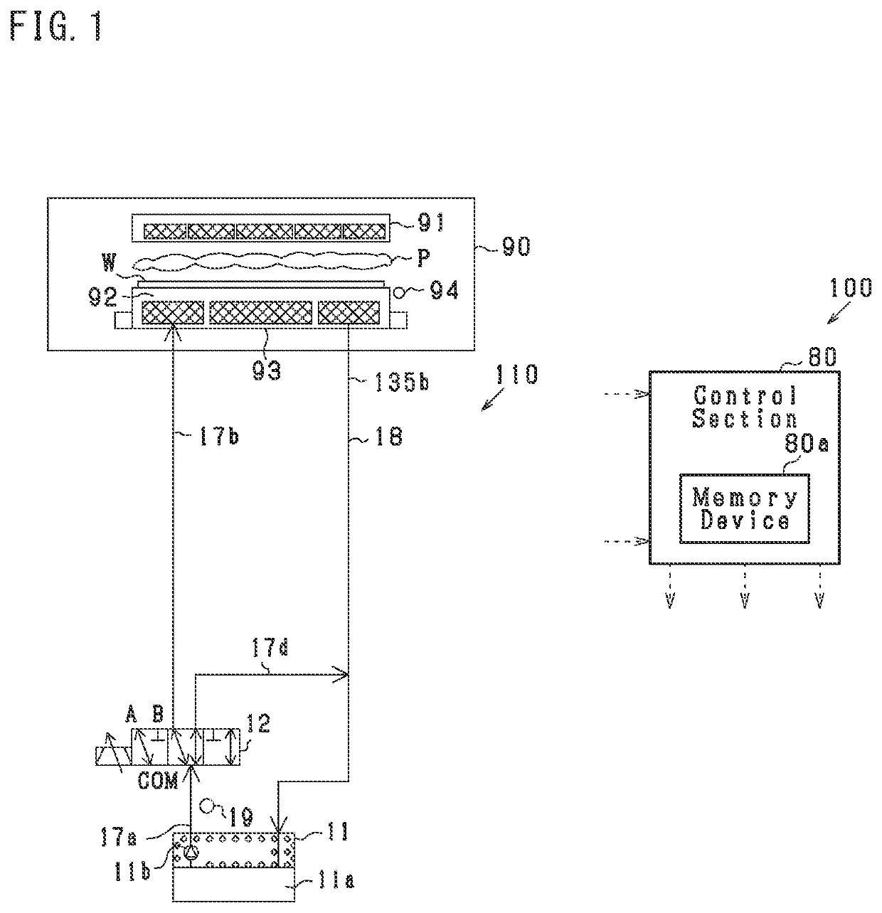
[0059]As shown in FIG. 1, a temperature control system 100 includes a first circulation circuit 110, a control section 80, etc.

[0060]The first circulation circuit 110 is a circuit through which a first heat transfer medium circulates. The first heat transfer medium (heat transfer medium) is, for example, a liquid composed of ethylene glycol (60%) and water (40%). The first heat transfer medium is relatively inexpensive. The first circulation circuit 110 includes a first chiller 11, a temperature sensor 19, a first distribution valve 12, etc.

[0061]The first chiller 11 (adjustment apparatus) includes a tank 11a, a pump 11b, etc. The first chiller 11 can adjust the temperature of the first heat transfer medium to −25° C. to 95° C. Th...

second embodiment

[0081]A second embodiment will now be described. In the following description, the difference between the second embodiment and the first embodiment will be mainly described. Notably, portions identical with those of the first embodiment are denoted by the same reference numerals, and their description will not be repeated.

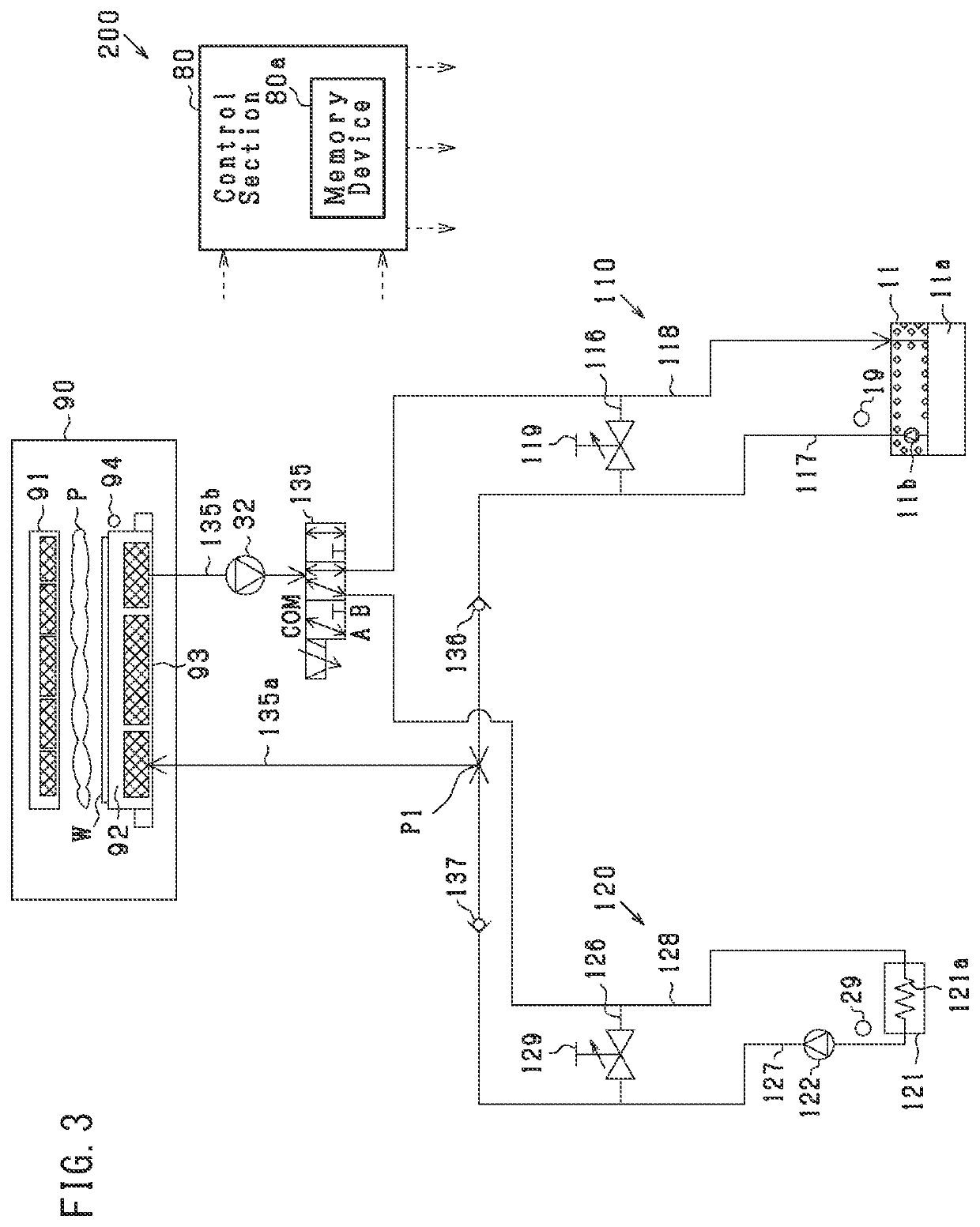
[0082]As shown in FIG. 3, a temperature control system 200 includes a first circulation circuit 110, a second circulation circuit 120, the control section 80, etc. The first circulation circuit 110 is a circuit through which the above-described first heat transfer medium circulates. The second circulation circuit 120 is a circuit through which a second heat transfer medium circulates. The second heat transfer medium is the same liquid as the first heat transfer medium. Namely, the first circulation circuit 110 and the second circulation circuit 120 are circuits through which the above-described first heat transfer medium (common heat transfer medium) used in commo...

third embodiment

[0103]A third embodiment will now be described. In the following description, the difference between the third embodiment and the second embodiment will be mainly described. Notably, portions identical with those of the first and second embodiments are denoted by the same reference numerals, and their description will not be repeated.

[0104]As shown in FIG. 4, a temperature control system 300 of the present embodiment is identical with the temperature control system 200 of the second embodiment except that the second distribution valve 135 is replaced with a third distribution valve 335.

[0105]The third distribution valve 335 (adjustment section) is a four-way valve having a common port, an H port, a B port, and a C port. The flow passage 118 is connected to the C port. The flow passage 118 is connected to the tank 11a of the first chiller 11. A flow passage 239 is connected to the B port. The flow passage 239 is connected to the flow passage 135a at the merging point P1. A third chec...


PUM


Abstract

A temperature control system is used for controlling a temperature of a control target to a target temperature that changes with lapse of time. The system includes: a first adjustment apparatus that includes a first tank that stores a first heat transfer medium, adjusts the temperature of the first heat transfer medium to a first set temperature, and supplies the temperature-adjusted first heat transfer medium; a first circulation circuit through which the first heat transfer medium flows from the first adjustment apparatus to a first flow-through path and returns to the first adjustment apparatus; an adjustment section that adjusts an amount of heat supplied from the first flow-through path to the control target; a memory that stores a relation between the lapse of time and the target temperature; and a controller.

Description

CROSS REFERENCE TO RELATED APPLICATION[0001]The present application is based on Japanese Patent Application No. 2019-209955 filed on Nov. 20, 2019, the entire content of which is incorporated herein by reference.BACKGROUNDTechnical Field[0002]The present disclosure relates to a temperature control system for controlling the temperature of a control target.Description of the Related Art[0003]Conventionally, there has been known a cooling apparatus which detects the temperature of a cooling liquid supplied to an object to be cooled (supply-side detected temperature) and performs feedback control such that the supply-side detected temperature becomes equal to a target temperature (see Japanese Patent No. 5445766). The cooling apparatus disclosed in Japanese Patent No. 5445766 detects the temperature of the cooling liquid returned from the object to be cooled (return-side detected temperature), obtains the degree of change of the return-side detected temperature with time, and changes t...

Claims


Application Information

Patent Timeline
IPC IPC(8): F25D29/00F25D17/02
CPCF25D29/001F25D17/02F25D2303/085F25D2400/34F25D2700/16F25D2600/02F25D2700/121F25D2700/123F25D2500/04G05D23/20H01L21/67248H01L21/67109G05D23/1904G05D23/1333G05D23/1902G05D23/1919G05D23/32
Inventor ITO, AKIHIROKOKUBO, NORIOKOUKETSU, MASAYUKIHASEGAWA, ISAHIRONAKAZAWA, TOSHIHARUTAKANASHI, KEISUKEFUKUSUMI, YUKIHIRO
Owner CKD
Why Eureka
Try Eureka