
Lure and bait system

a technology of lure and bait, which is applied in the field of lure and bait holding system, can solve the problems of lure wear and bait disintegration, attractant wear and tear, and can be a problem, and achieve the effect of rapid and easy reinforcemen

Inactive Publication Date: 2007-08-09
DING GOES
View PDF92 Cites 22 Cited by
  • Summary
  • Abstract
  • Description
  • Claims
  • Application Information

AI Technical Summary

Benefits of technology

The apparatus maintains the shape and attractant properties of the bait or lure, reducing preparation time and extending its usability by deforming around the bait or lure, while the embedded attractants ensure continuous attraction without washing away, even in challenging environments.

Problems solved by technology

In both commercial and recreational fishing, lure wear and bait disintegration can be a problem where the bait or lure is subjected to successive hits, grabs or strikes, or where the bait or lure is suspended in water for considerable periods of time.
Where natural teasers are used, again the problem of disintegration becomes an issue.
In the case of lures damage to the lure requires replacing the lure and the attractant wears from the lure when the lure is suspended in water for an extended period.
However, the preparation of each teaser is very time consuming, often taking from 10 to 30 minutes and, where multiple teasers are used, this can involve significant preparation time and delays.
Whilst these apparatus can also act as teasers, because fish-attracting aroma and scent can be released therefrom, the apparatus are not designed to enhance visual attraction, in that they retain essentially a bag shape once bait has been inserted therein.
This makes manufacture of the sleeve quite complex.
Again, the manufacture of the bag is rendered more complex.

Method used


Image

  • Lure and bait system
  • Lure and bait system
  • Lure and bait system

Examples


Embodiment Construction

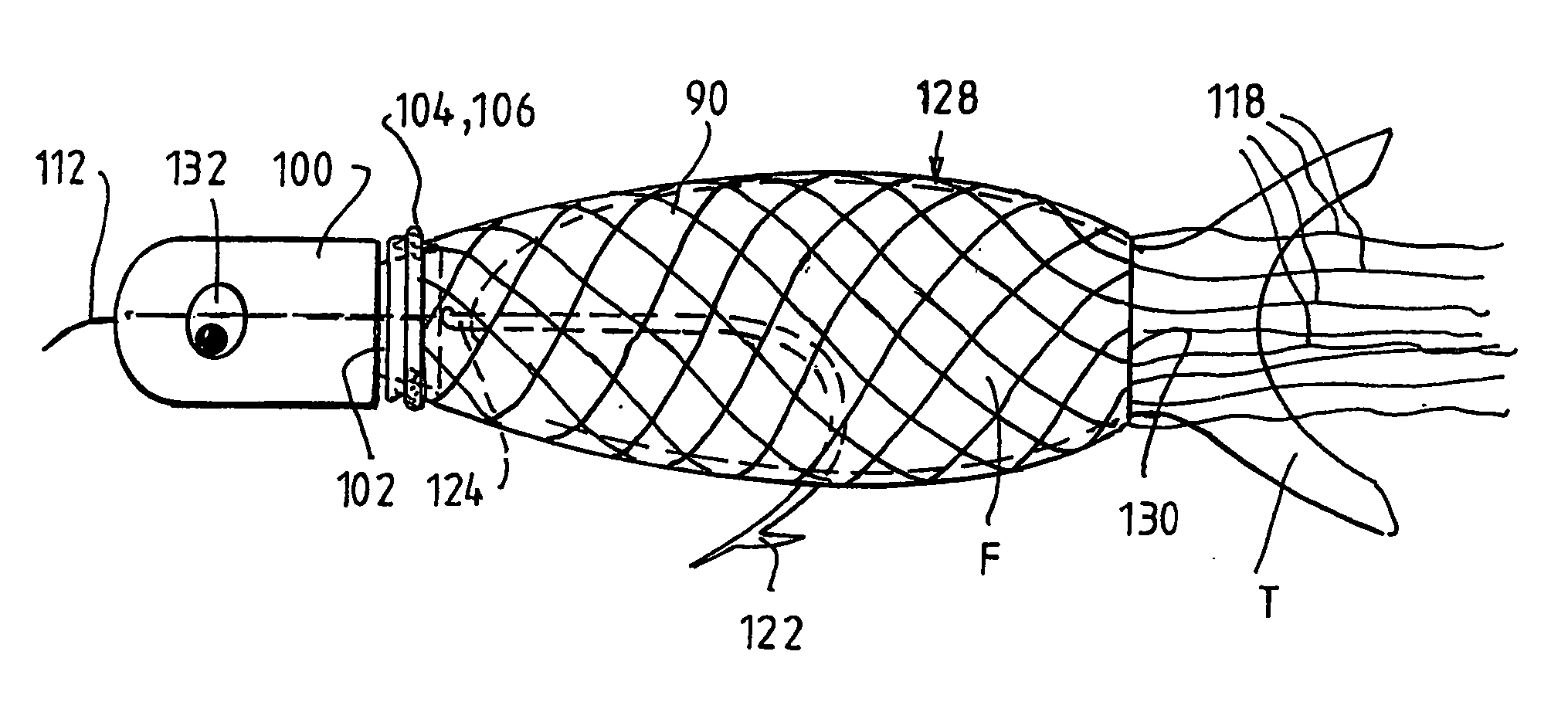
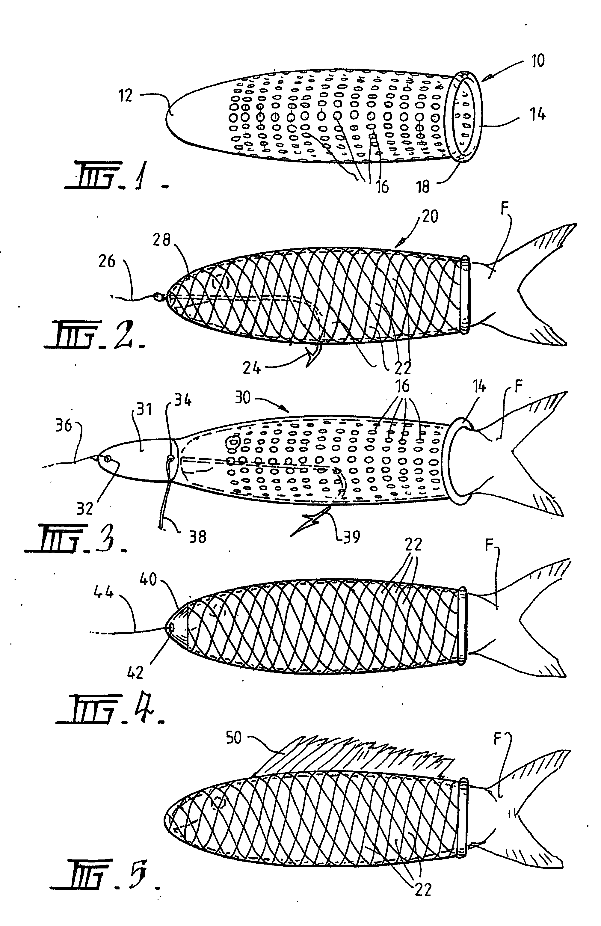
[0033] Referring firstly to FIG. 1, a lure and / or bait holding apparatus is shown in the form of an elongate sock sleeve 10. The sock sleeve has a closed end 12 and an opposite open end 14. A plurality of apertures in the form of holes 16 are defined in the sock sleeve as shown.

[0034] The open end is typically reinforced by a circumferential back-fold or roll 18 of the sleeve 10. This allows for repeated insertion and removal of bait and lures to and from the sleeve (eg. using an applicator as shown in FIGS. 17 and 18), without the sleeve deteriorating at that end (eg. by tearing). The closed end may also be reinforced, for example, by being of increased thickness (as specified during moulding) to prevent the bait or lure from being pushed out at that end during insertion, and optionally to allow for line and hook attachment etc.

[0035] Typically the sock sleeve is formed from an elastomeric material having shape memory, such as an elastomeric polymer (eg. a natural or synthetic ru...


PUM


Abstract

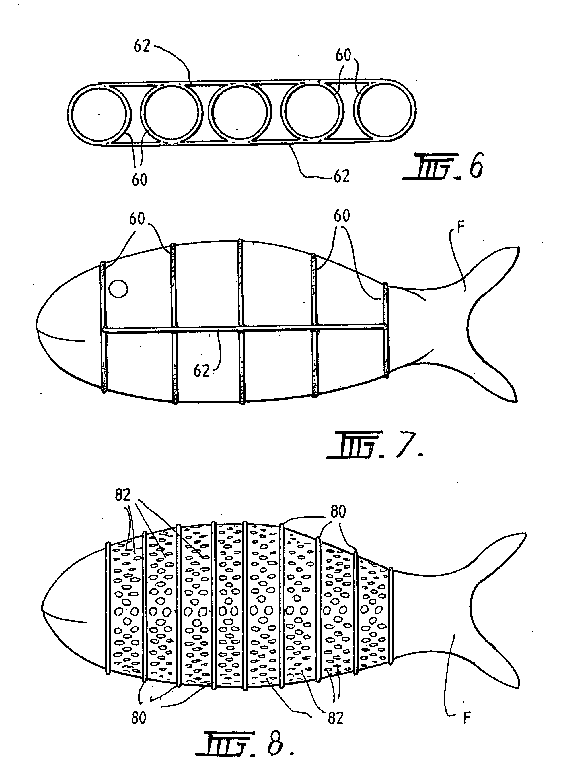
A bait holding apparatus includes a deformable receptacle 10 into which the bait can be placed such that the receptacle can deform around the bait. A plurality of apertures 16 are defined in the receptacle such that, when the bait is placed therein, the predator can sense the bait via the apertures. The apparatus can have a shape that enables it to surround the bait in a close-facing relationship. A closure 100 can be located in an open end of the receptacle, with the closure optionally having passage(s) 108,110 therethrough. Alternatively, the apparatus can be a plurality of interconnected ties. A method for forming the apparatus includes the steps of dipping a mandrel into molten material for the sleeve; removing the mandrel and allowing the sleeve to solidify around the mandrel; forming a plurality of apertures in the sleeve, either whilst on the mandrel, or once removed therefrom.

Description

CROSS-REFERENCE TO RELATED PATENT APPLICATIONS [0001] This application is a continuation-in-part of copending U.S. patent application Ser. No. 10 / 505,310 filed Aug. 20, 2004, which is a U.S. National Stage application under 35 U.S.C. 371 of PCT / AU03 / 00226 filed Feb. 21, 2003, which claims the priority of Australian Patent Application Nos. PS 0718 filed Feb. 22, 2002 and PS 1343 filed Mar. 25, 2002.FIELD OF THE DISCLOSURE [0002] The present disclosure relates to a lure and bait holding system developed primarily, though not exclusively, for holding and optionally reinforcing, storing or housing lures and / or bait for use in fishing and related pursuits. BACKGROUND TO THE DISCLOSURE [0003] In both commercial and recreational fishing, lure wear and bait disintegration can be a problem where the bait or lure is subjected to successive hits, grabs or strikes, or where the bait or lure is suspended in water for considerable periods of time. [0004] In deep-sea fishing for large fish, such a...

Claims


Application Information

Patent Timeline
Patent Type & Authority Applications(United States)
IPC IPC(8): A01K83/06A01K97/04A01K85/01
CPCA01K83/06
Inventor KALAZICH, GRAHAM
Owner DING GOES
Learn More