
Overlapping printed circuit boards and electronic device including same

a printed circuit board and electronic device technology, applied in cross-talk/noise/interference reduction, electrical apparatus casings/cabinets/drawers, instruments, etc., can solve the problems of electromagnetic interference (emi) that interferes with the normal operation of electronic components, the internal space of the electronic device is more, and the width of the wire is expanded. , to achieve the effect of increasing the wiring density

Active Publication Date: 2022-05-10
SAMSUNG ELECTRONICS CO LTD
View PDF27 Cites 0 Cited by
  • Summary
  • Abstract
  • Description
  • Claims
  • Application Information

AI Technical Summary

Benefits of technology

The patent provides a way to make sure that printed circuit boards are rigid enough, and to securely connect them to each other without increasing the size of the circuit connections. This makes it easy to reinforce certain areas of the circuit boards and ensures that they are secure and reliable.

Problems solved by technology

A printed circuit board may include, for example, an area having that is relatively thin, which may be more likely than other areas to be damaged (cracked) due to an impact when the printed circuit board is coupled to or separated from an electronic device.
However, this may consume more of the internal space in the electronic device and make it difficult to install other elements.
Due to current flow, an electric field is formed in the signal lines, and this electric field causes electromagnetic interference (EMI) that interferes with the normal operation of the electronic components by introducing noise to a nearby electronic component or signals transmitted to another nearby signal line.
In this regard, it is becoming more difficult to design the signal lines in a printed circuit board (e.g., the area formed in a relatively narrow width in the printed circuit board).

Method used


Image

  • Overlapping printed circuit boards and electronic device including same
  • Overlapping printed circuit boards and electronic device including same
  • Overlapping printed circuit boards and electronic device including same

Examples


Embodiment Construction

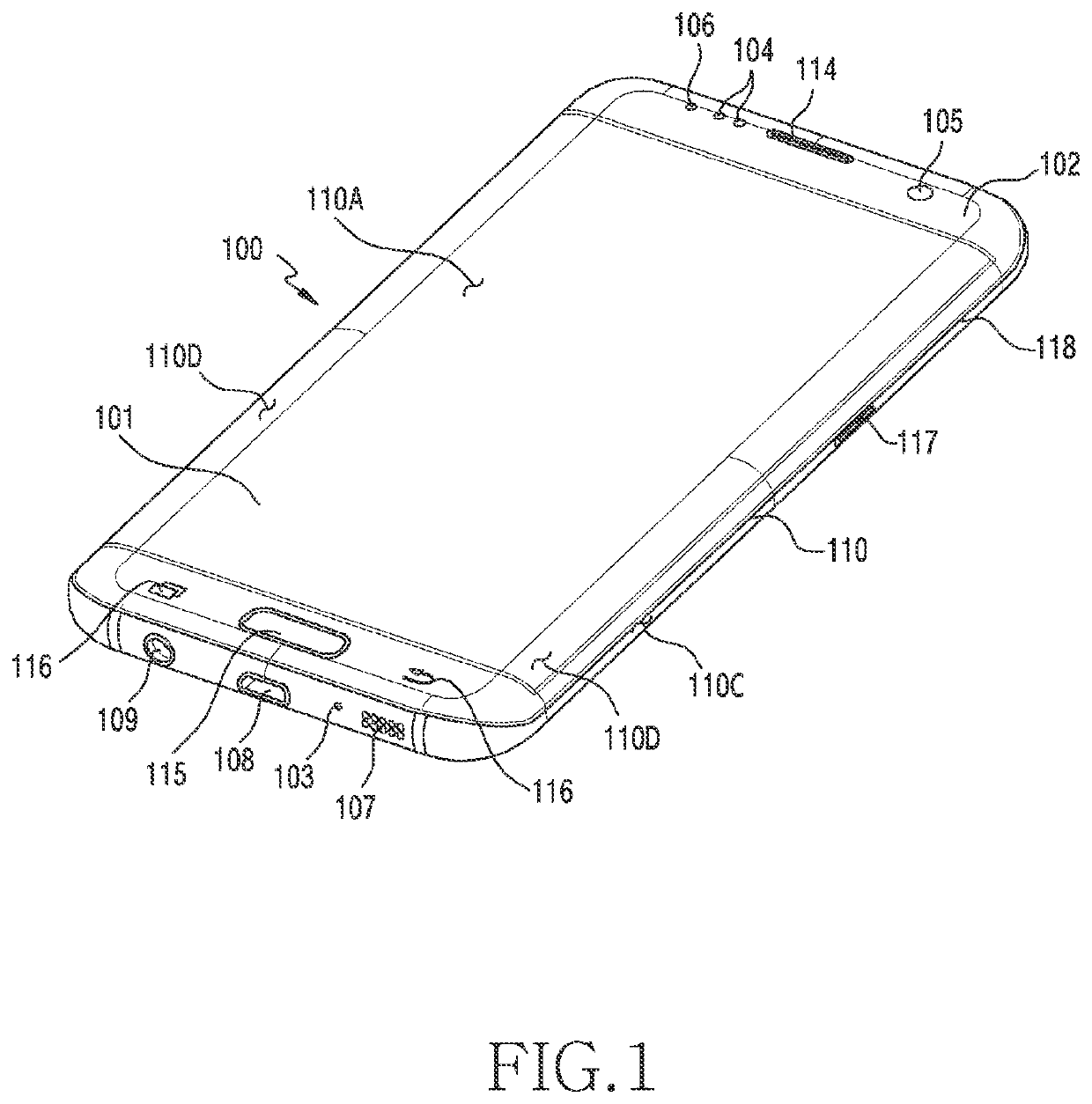
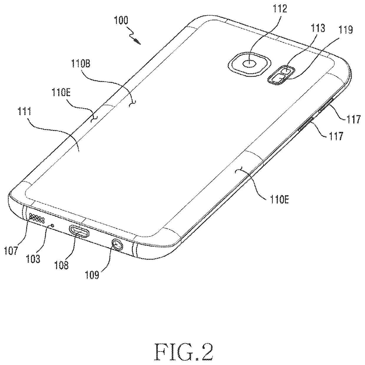
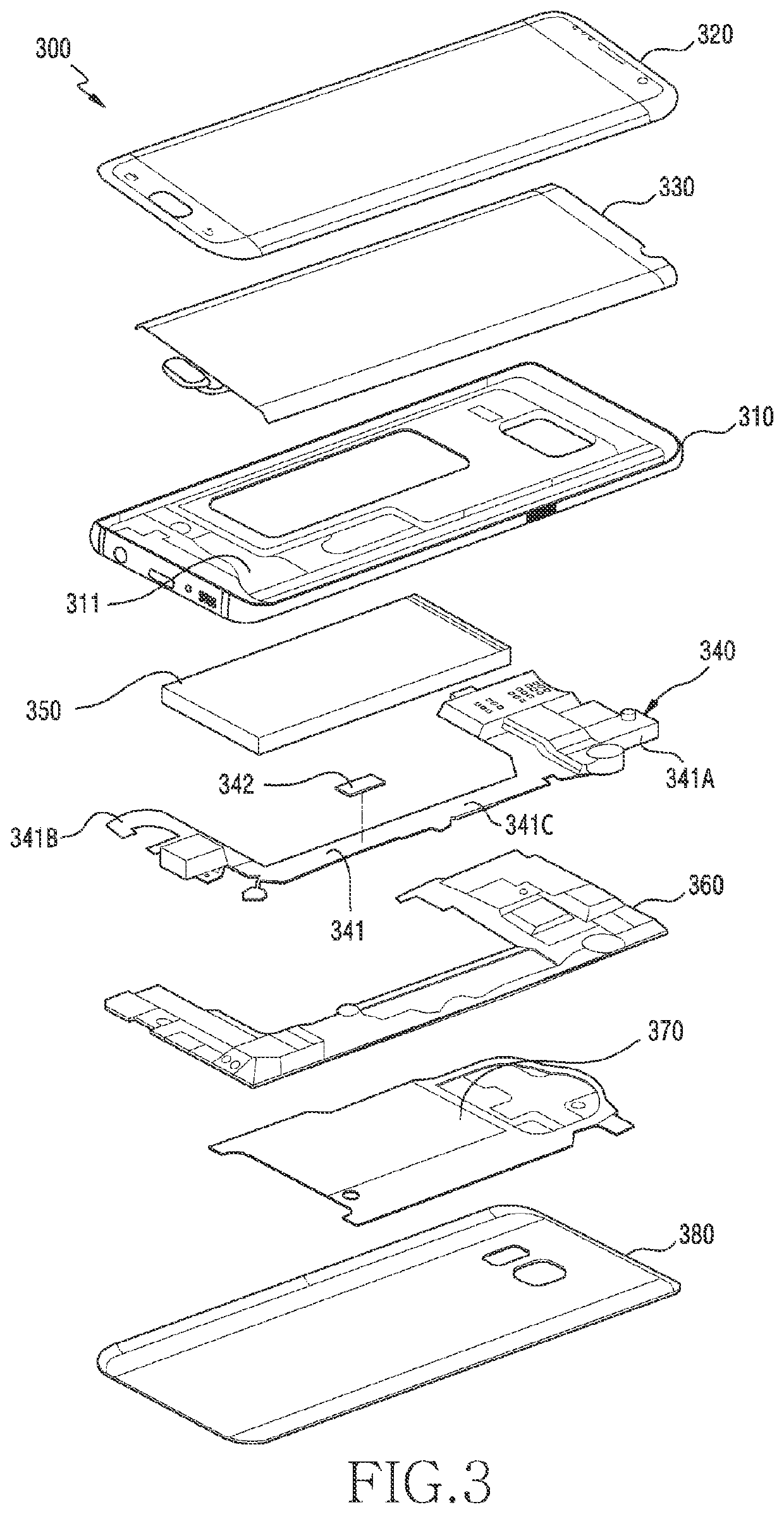
[0036]Hereinafter, certain embodiments of the disclosure will be described with reference to the accompanying drawings. The certain embodiments and the terms used herein are not intended to limit the technical features disclosed herein to specific embodiments, and should be understood to include various modifications, equivalents, and / or alternatives to the corresponding embodiments. In describing the drawings, similar reference numerals may be used to designate similar constituent elements. The singular form of a noun corresponding to an item may include one item or a plurality of items unless the relevant context clearly indicates otherwise. In the disclosure, the expression “A or B”, “at least one of A and B”, “at least one of A or B”, “A, B, or C”, or “at least one of A, B, or C” may include all possible combinations of items enumerated together. The expression “a first”, “a second”, “the first”, or “the second” may modify corresponding elements regardless of the order or import...


PUM

PropertyMeasurementUnit
areasaaaaaaaaaa
thicknessesaaaaaaaaaa

Abstract

According to an embodiment of the disclosure, an electronic device comprises a first printed circuit board including a first electrical terminal exposed on one face of a first area, a second electrical terminal exposed on the one face of a second area and insulated from the first electrical terminal, and a first ground terminal exposed on the one face of a third area formed between the first area and the second area, the third area having a width narrower than a width of the first area or the width of the second area; and a second printed circuit board including a third electrical terminal exposed on one face of a fourth area, a fourth electrical terminal exposed on the one face of a fifth area and electrically connected to the third electrical terminal, and a second ground terminal exposed on the one face of a sixth area located between the fourth area and the fifth area, wherein the second printed circuit board is disposed on the first printed circuit board to overlap the third area, the first electrical terminal and the third electrical terminal are electrically coupled to each other, the second electrical terminal and the fourth electrical terminal are electrically coupled to each other, and the first ground terminal and the second ground terminal are electrically coupled to each other.

Description

CROSS-REFERENCE TO RELATED APPLICATION(S)[0001]This application is a continuation application of prior application Ser. No. 16 / 413,797, filed on May 16, 2019, which is based on and claims priority under 35 U.S.C. § 119(a) of a Korean patent application Serial number 10-2018-0061270, filed on May 29, 2018, in the Korean Intellectual Property Office, the disclosure of which is incorporated by reference herein in its entirety.BACKGROUND1. Field[0002]Certain embodiments relate to overlapping printed circuit boards and an electronic device including the printed circuit boards.2. Description of Related Art[0003]The above information is presented as background information only to assist with an understanding of the disclosure. No determination has been made, and no assertion is made, as to whether any of the above might be applicable as prior art with regard to the disclosure.[0004]With the development of digital technologies, electronic devices are being produced in various forms such as ...

Claims


Application Information

Patent Timeline
Patent Type & Authority Patents(United States)
IPC IPC(8): H05K1/14H05K1/11H05K5/00H05K1/02H05K3/46H04M1/02H01Q1/24H05K1/03H04M1/03
CPCH05K1/144H01Q1/243H04M1/0264H04M1/0277H05K1/025H05K1/0243H05K1/0366H05K1/115H05K3/4644H05K5/0086H04M1/03H05K2201/042H05K2201/09027H05K2201/1009H05K2201/10098H05K2201/10121H05K2201/10151H05K2201/10234H01Q1/38H05K1/141G06F1/183H04M1/0262H04M1/185Y02E60/10H05K1/0271H05K1/0216H05K1/111
Inventor PARK, JINYONGKIM, TAEWOOLEE, HYEONGJUMIN, BONGKYUPARK, JUNGSIKYUN, HYELIM
Owner SAMSUNG ELECTRONICS CO LTD
Learn More