
Data input method and apparatus, and liquid crystal display device using the same

Inactive Publication Date: 2007-08-02
SAMSUNG DISPLAY CO LTD
View PDF4 Cites 7 Cited by
  • Summary
  • Abstract
  • Description
  • Claims
  • Application Information

AI Technical Summary

Benefits of technology

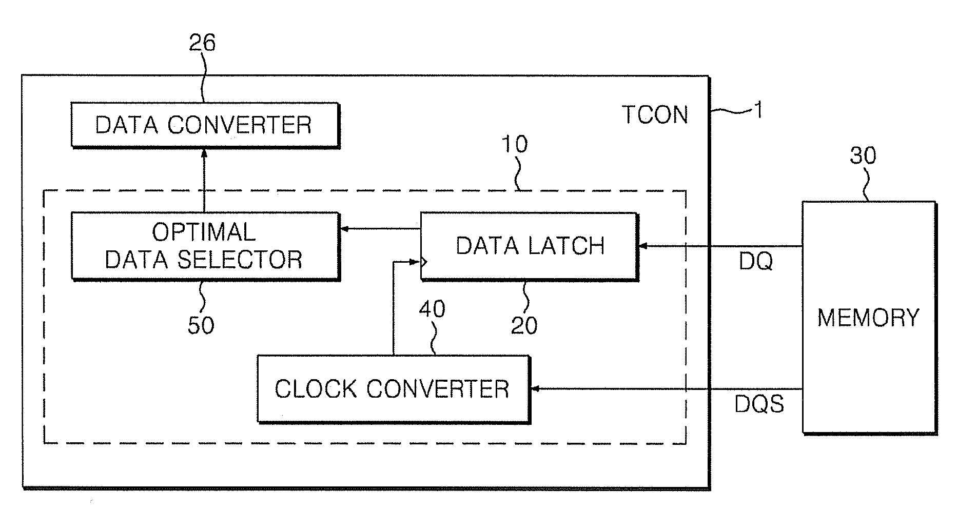
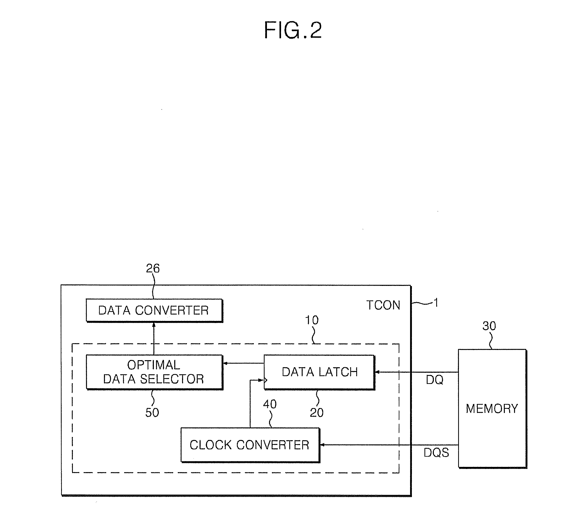
[0017]The data input part may include a clock converter inputting a transmission clock transmitted together with the data from the memory and converting the transmission clock into a plurality of clocks having different phases, a data latch latching the data from the memory according to the plurality of clocks from the clock converter, and an optimal data selector setting the clock of the optimal margin by comparing a plurality of latched data generated from the data latch with original data from the memory and selectively generating data latched according to the clock of the optimal margin.
[0018]The memory stores original check data, the data latch latches the original check data from the memory according to the plurality of clocks, and the optimal data selector detects identical check data by comparing a plurality of latched check data generated from the data latch with original check data from the memory and sets a clock used in the data latch to latch detected identical check data as the clock of the optimal margin.
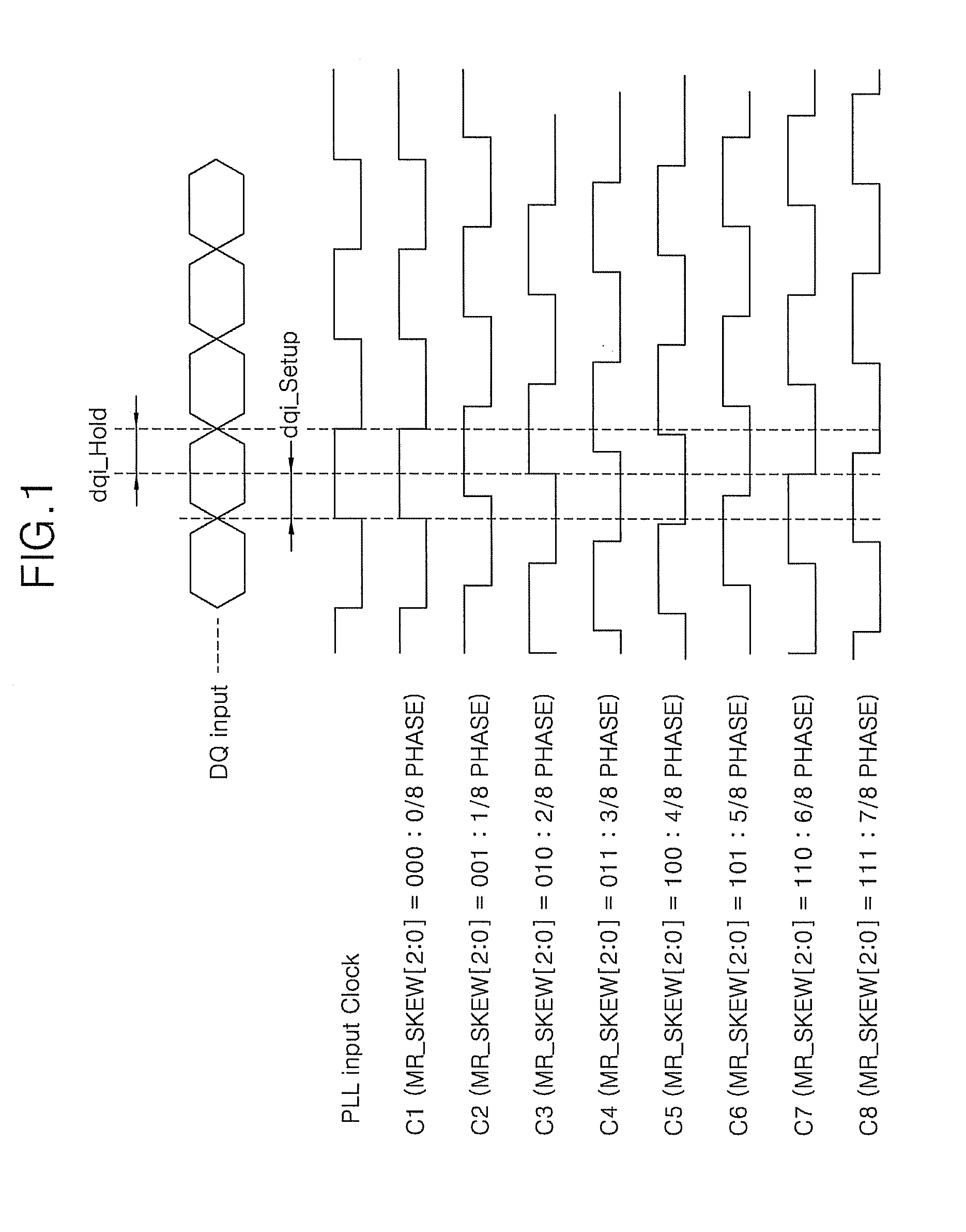
[0019]The optimal data selector detects a plurality of latched check data identical to the original check data among the plurality of the latched check data, detects a plurality of clocks used for latching the plurality of the detected identical check data, and sets a clock having any one phase value among the plurality of detected clocks as the clock of the optimal margin. The optimal data selector sets a clock having a middle phase value among

Problems solved by technology

However, even if a phase value of the clock is set so that the center of the data is aligned with the edge of the clock, a timing skew between the data and the clock deviates due to ambient temperature, clock delay and circuit deviation, thereby inducing an error during data latch.

Method used


Image

  • Data input method and apparatus, and liquid crystal display device using the same
  • Data input method and apparatus, and liquid crystal display device using the same
  • Data input method and apparatus, and liquid crystal display device using the same

Examples


Embodiment Construction

[0029]The invention will now be described more fully hereinafter with reference to the accompanying drawings, in which exemplary embodiments of the invention are shown. This invention may, however, be embodied in many different forms and should not be construed as limited to the embodiments set forth herein. Rather, these embodiments are provided so that this disclosure will be thorough and complete, and will fully convey the scope of the invention to those skilled in the art. Like reference numerals refer to like elements throughout.

[0030]It will be understood that, although the terms first, second, third etc. may be used herein to describe various elements, components, regions, layers and / or sections, these elements, components, regions, layers and / or sections should not be limited by these terms. These terms are only used to distinguish one element, component, region, layer or section from another element, component, region, layer or section. Thus, a first element, component, reg...


PUM


Abstract

For a data input method and apparatus capable of latching data from a memory by using a clock of optimal timing, and a liquid crystal display device using the same, a clock of an optimal margin is set by reading out check data stored in a memory, and the check data read out from the memory is latched and generated according to the set clock of the optimal margin.

Description

[0001]This application claims priority to Korean Patent Application No. 2006-0008925, filed on Jan. 27, 2006 and all the benefits accruing therefrom under 35 U.S.C. §119, and the contents of which in its entirety are herein incorporated by reference.BACKGROUND OF THE INVENTION[0002]1. Field of the Invention[0003]The present invention relates to a data input method and apparatus, and a liquid crystal display device using the same, and more particularly, to a data input method and apparatus capable of preventing a data input error caused by temperature and circuit deviation, and a liquid crystal display device using the same.[0004]2. Description of the Related Art[0005]Flat panel display devices include a liquid crystal display (“LCD”) device using liquid crystals, a plasma display panel (“PDP”) using a discharge of an inert gas, an organic light emitting device (“OLED”), etc. The PDP is used for large-sized TVs, whereas the OLED is applied to small-sized products. Meanwhile, the LCD ...

Claims


Application Information

Patent Timeline
IPC IPC(8): G11C29/00
CPCG09G3/006G09G3/3677G09G3/3688G09G5/008G09G2310/061G11C29/50012G09G2320/0673G09G2360/18G11C29/02G11C29/022G11C29/028G09G2320/0233E06B3/26305E06B3/26347E06B3/301E06B3/4609E06B7/14E06B2003/26312E06B2009/527
Inventor PARK, JONG HYON
Owner SAMSUNG DISPLAY CO LTD
Learn More