Rate locked loop radar timing system

a timing system and lock loop technology, applied in the field ofradar timing circuits, can solve the problems of easy to assume that the timing circuit is somehow perfect, the accuracy of the two-oscillator technique is limited, and the accuracy of the phase slip is not easy to measure accurately

Inactive Publication Date: 2007-08-02
MCEWAN TECH
View PDF13 Cites 22 Cited by
  • Summary
  • Abstract
  • Description
  • Claims
  • Application Information

AI Technical Summary

Benefits of technology

[0012] A final aspect of the present invention provides for a radar, laser or time domain reflectometry (TDR) system that can include, but is not limited to: a transmitter triggered by a first clock signal, a receiver gated by a second clock signal, a phase detector responsive to phase between the first and second clock signals for producing a phase signal, a differentiator for producing a derivative signal from the phase signal, a phase control for adjusting the phase of the second clock signal; an...

Problems solved by technology

The accuracy of the two-oscillator technique is limited by the differential and integral linearity of the phase slip between the two oscillators.
The accuracy of the phase slip is not easy to measure accurately and it is also easy to assume it is somehow perfect.
Unfortunately, precision long range systems require extremely high accuracy, on the order of picoseconds, at offset frequencies on the o...

Method used


Image

  • Rate locked loop radar timing system
  • Rate locked loop radar timing system
  • Rate locked loop radar timing system

Examples


Embodiment Construction

[0024] A detailed description of the present invention is provided below with reference to the figures. While illustrative component values and circuit parameters are given, other embodiments can be constructed with other component values and circuit parameters. All U.S. patents and copending U.S. applications cited herein are herein incorporated by reference in their entirety.

General Description

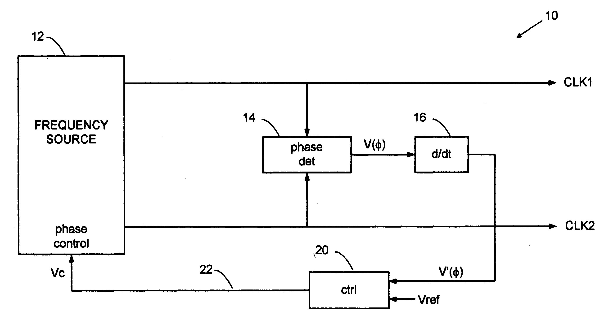
[0025] The present invention overcomes the bandwidth limitations of a PLL controller by directly controlling the phase slip rate on a continuous and instantaneous basis. A beneficial example embodiment, as disclosed herein, employs a phase detector coupled directly between two oscillators, rather than through counter chains that are customary in PLL circuits, to produce a voltage proportional to instantaneous phase. When the phase between the oscillators slips at a constant rate, because of the offset frequency, the phase detector output is a linear voltage ramp that increases for increas...


PUM


Abstract

A rate locked loop (RLL) regulates phase slip between two clock signals to provide precision timing for radar, TDR and laser ranging systems. Two clocks having a small mutual frequency offset exhibit a slowing changing relative phase, or phase slip, that produces a stroboscopic time expansion effect in a ranging system. A phase detector converts clock phase to voltage and the voltage is differentiated to provide a rate-of-change signal to a loop controller that precisely regulates the rate-of-phase change. The RLL controls a VCO to produce a constant, linear phase slip having phase errors below the time equivalent of 1-picosecond.

Description

BACKGROUND OF THE INVENTION [0001] 1. Field of the Invention [0002] The present invention relates to radar timing circuits, and more particularly to precision swept delay circuits for expanded time ranging systems. It can be used to generate a swept-delay dock for sampling radar, time domain reflectometry (TDR) and laser systems. [0003] 2. Description of Related Art [0004] High accuracy pulse-echo ranging systems, such as wideband and ultra-wideband pulsed radar, pulsed laser rangefinders, and time domain reflectometers, sweep a timing circuit across a range of delays. The timing circuit controls a receiver sampling gate such that when an echo signal coincides with the temporal location of the sampling gate, a sampled echo signal is obtained. The echo range is then determined from the timing circuit, so high timing accuracy is essential. A beneficial feature for high accuracy is time expansion, whereby the receiver sampling rate is set to a slightly lower rate than the transmit puls...

Claims


Application Information

Patent Timeline
IPC IPC(8): H03D3/24
CPCG01S7/28G04F10/06H03L7/093H03L7/085H03L7/0812
Inventor MCEWAN, THOMAS EDWARD
Owner MCEWAN TECH
Why Eureka
Try Eureka