
Heat dissipation fan

a technology of heat dissipation fan and fan blade, which is applied in the direction of liquid fuel engines, instruments, machines/engines, etc., can solve the problems of insufficient heat dissipation efficiency of turbo fans, and insufficient heat dissipation efficiency of servers, etc., to achieve significant heat dissipation

Inactive Publication Date: 2007-07-26
ASUSTEK COMPUTER INC
View PDF1 Cites 23 Cited by
  • Summary
  • Abstract
  • Description
  • Claims
  • Application Information

AI Technical Summary

Benefits of technology

[0007]In view of the problems and shortcomings of the prior art, the objective of the invention is to provide a heat dissipation fan used in a framed server, thus raising the heat dissipation efficiency of the server significantly.
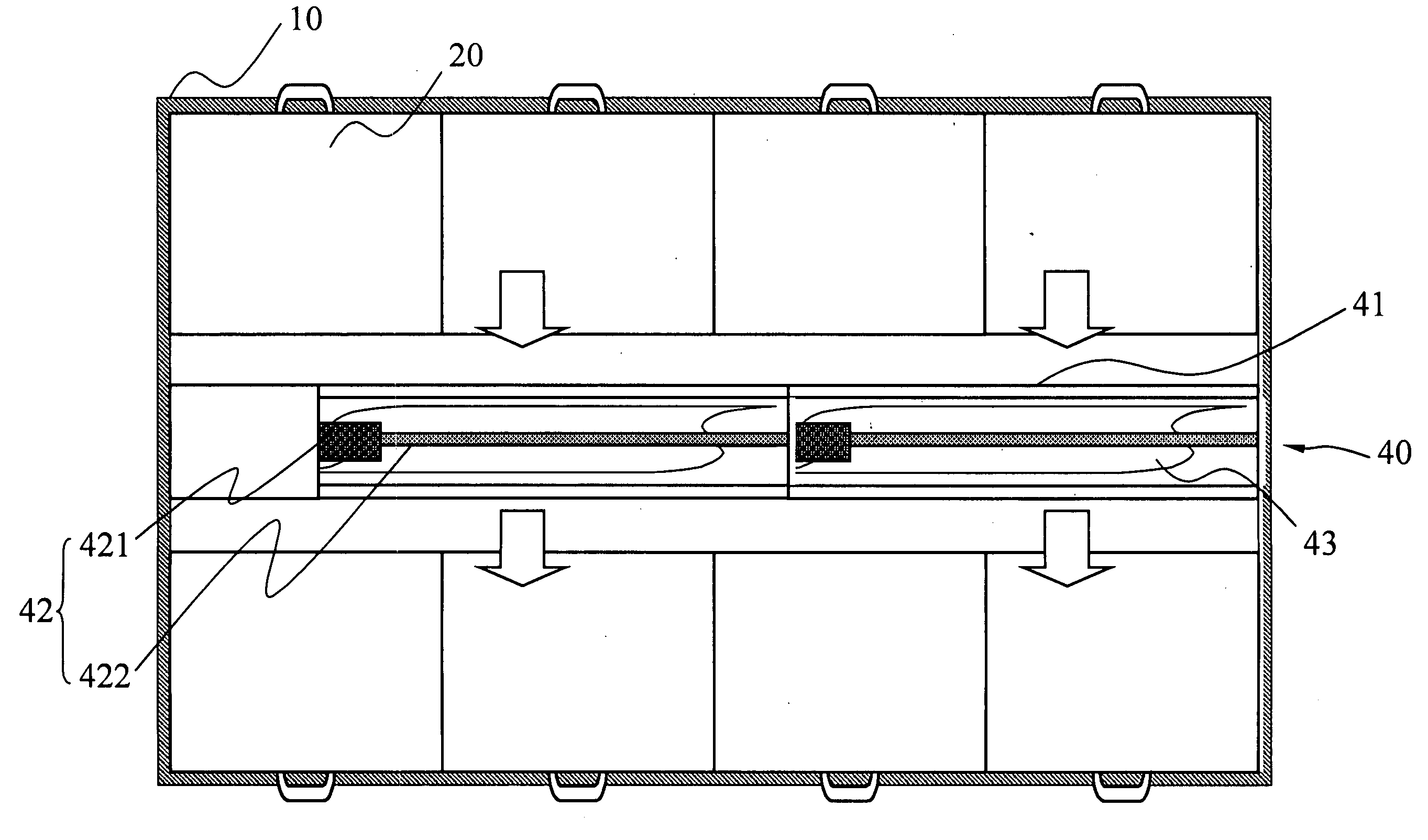
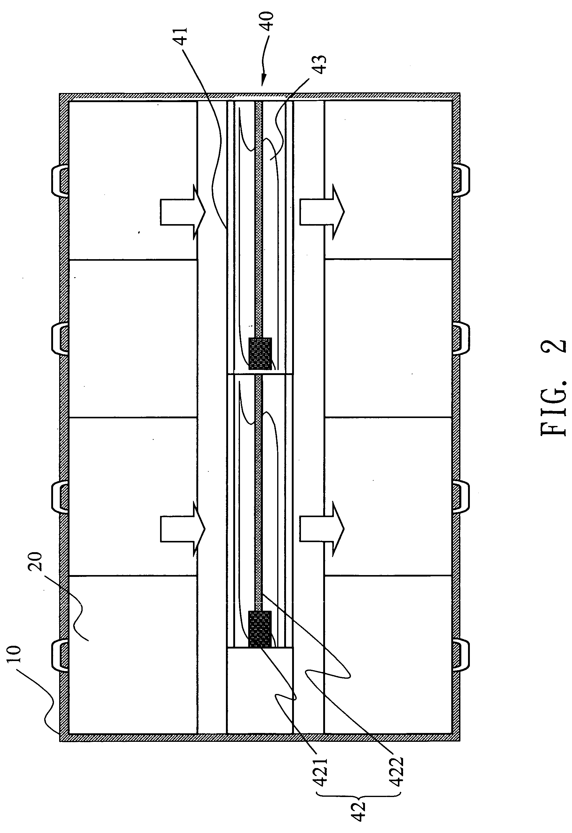
[0010]Thus, the objective of the invention is achieved through the specially designed rotation axis having extension portion of smaller diameter, so as to raise the air-cutting area of the fan blade significantly. Thus, the area of the air cut by the fan blades extend outward from the main portion and extension portion is much larger than the area cut only by the fan blades extending outward from the main portion. As such, the increase of the air-cutting area of the fan blade can be realized by increasing the length of the extension portion of the heat dissipation fan, so as to raise the heat dissipation efficiency of the server studded with various electronic devices and having limited heat dissipation space, so that the various electronic devices in the server may function normally.

Problems solved by technology

In general, a server frame is of a specific height, thus the spacing between the electronic devices is rather limited.
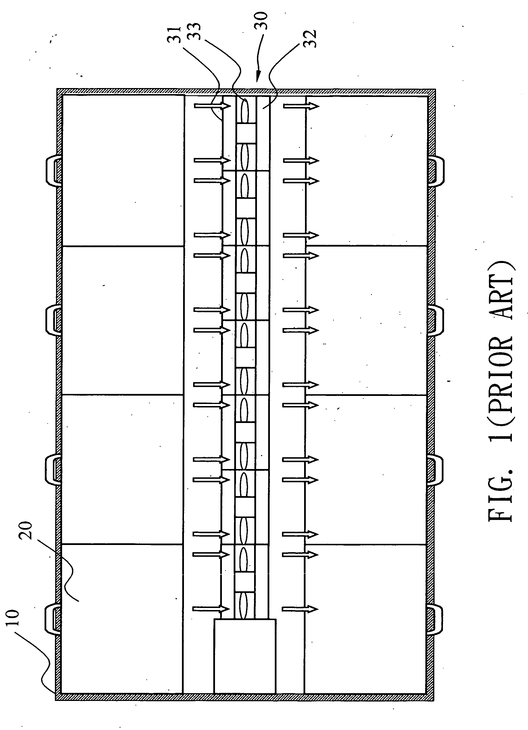
However, since the length of the rotation axis 32 is rather short, thus the area of the air cut through by the fan blade 33 used to carry out the heat through its rotation is rather limited.
As such, the heat dissipation efficiency of the turbo fan 30 is not sufficient to meet the design requirements.

Method used


Image

  • Heat dissipation fan
  • Heat dissipation fan
  • Heat dissipation fan

Examples


Embodiment Construction

[0017]The purpose, construction, features, and functions of the invention can be appreciated and understood more thoroughly through the following detailed description with reference to the attached drawings.

[0018]In general, the server frame is designed to have a specific size, thus, usually, the space reserved for the electronic devices disposed therein is rather limited to increase the space utilization rate of a server. As such, the heat generated during the operation of the electronic devices is carried away by the heat dissipation device disposed in the server, so that the electronic devices may function normally and efficiently.

[0019]Usually, in a server, the heat dissipation fan is utilized as the heat dissipation device, thus the size of its heat dissipation efficiency depends on the air cutting area of the fan blade of the heat dissipation fan. So, presently, the heat dissipation in a server is realized through a turbo fan 30 in consideration of the limited space available....


PUM


Abstract

A heat dissipation fan used in a frame server, includes a rotation axis and a plurality of fan blades. The rotation axis is composed of a main portion and an extension portion, and the diameter of the main portion is greater than that of the extension portion. The fan blades extend outward from the rotation axis, and are utilized to drive the wind from one side of the rotation axis to the other side of the rotation axis in a direction perpendicular to the rotation axis. As such, greatly increase the air cutting area of the fan blades. In this manner, in the server frame studded with electronic devices and having very limited heat dissipation space, the heat dissipation efficiency of the server can be raised significantly, so that the electronic devices may function normally and efficiently.

Description

BACKGROUND[0001]1. Field of Invention[0002]The invention relates a heat dissipation fan used for a server, and in particular to a heat dissipation fan used for raising the heat dissipation efficiency of a server.[0003]2. Related Art[0004]Nowadays, due to the progress and development of science and technology, the prices of the various computer related equipment have been reduced significantly, and among them, the price of server is particularly so. As such, computer has become a daily necessity of most of the people.[0005]Usually, a server is composed of a main frame, which is provided with a plurality of server frames, and that are retractably disposed in the main frame. Thus, in the server frame a plurality of electronic devices are provided for use, such as the hard disk. In general, a server frame is of a specific height, thus the spacing between the electronic devices is rather limited. Due to the fact that heat is generated in the operation of the electronic device, thus, the ...

Claims


Application Information

Patent Timeline
IPC IPC(8): F04D19/00
CPCF04D25/12G06F1/20F04D29/282
Inventor CHIANG, CHIN-CHUN
Owner ASUSTEK COMPUTER INC
Learn More