
Apparatus for making controlled segregated phase domain structures

a phase domain structure and segregation technology, applied in the field of materials, can solve the problems of increasing costs, limiting the supply of indium, and arising supply constraints in the futur

Inactive Publication Date: 2007-07-12
HELIOVOLT CORP
View PDF99 Cites 15 Cited by
  • Summary
  • Abstract
  • Description
  • Claims
  • Application Information

AI Technical Summary

Benefits of technology

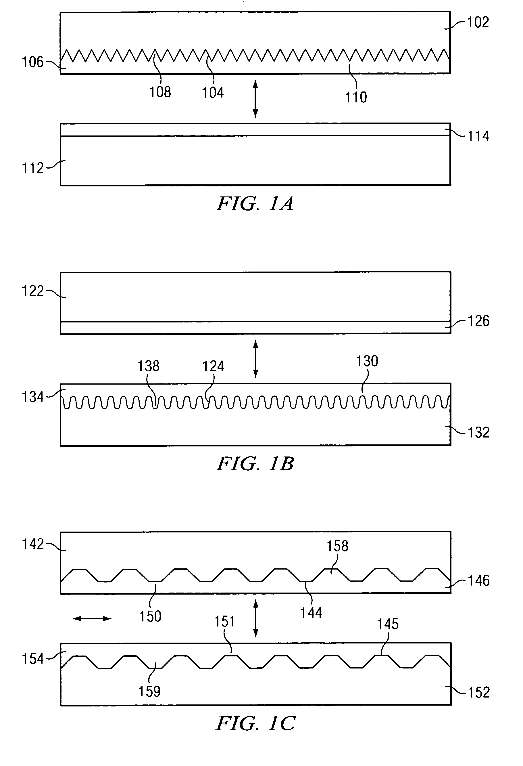
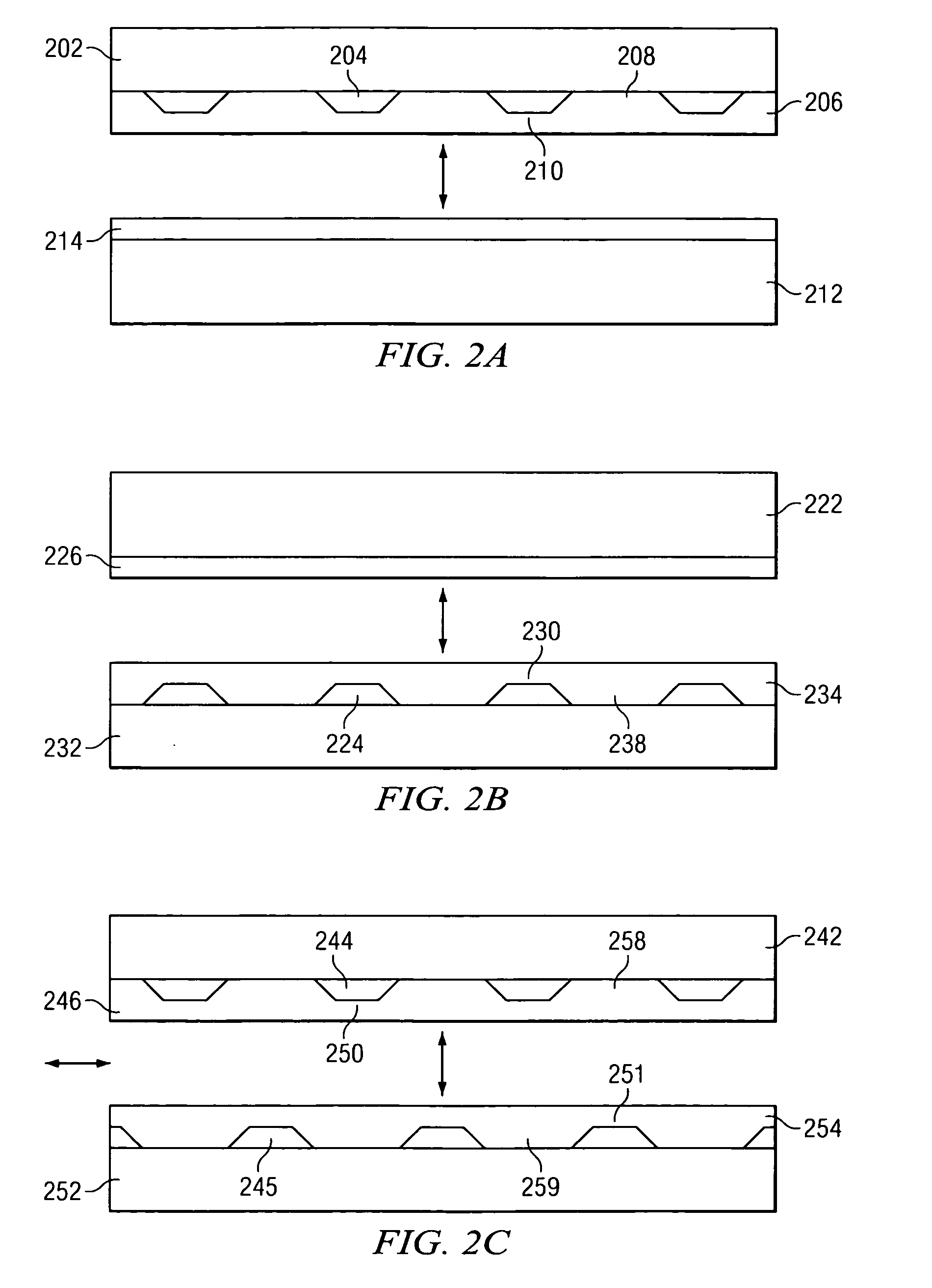
[0012] According to an embodiment of the invention, a process comprises: providing a first precursor on a first substrate; providing a second precursor on a second substrate; contacting the first precursor and the second precursor; reacting the first precursor and the second precursor to form a chemical reaction product; and moving the first substrate and the second substrate relative to one another to separate the chemical reaction product from at least one member selected from the group consisting of the first substrate and the second substrate, characterized in that, to control formation of a segregated phase domain structure within the chemical reaction product, a constituent of at least one member selected from the group consisting of the first precursor and the second precursor is provided in a quantity that substantially regularly periodically varies from a mean quantity with regard to basal spatial location.
[0013] According to another embodiment of the invention, a machine comprises: a first substrate; and a second substrate coupled to the first substrate, characterized in that, to control formation of a segregated phase domain structure within a chemical reaction product by controlling an amount of a constituent of a precursor that is present per unit surface area, at least one member selected from the group consisting of the first substrate and the second substrate defines a substantially regularly periodically varying relief with respect to basal spatial location.

Problems solved by technology

A concern with this technology is that raw material supply constraints are going to arise in the future as the production of CIS PV increases.
As the production of CIS PV approaches the large scale range of from approximately 10 gigawatts / year to approximately 100 gigawatts / year, indium supply constraints will become manifest.
These supply constraints will lead to increased costs.
Further, as the production of CIS PV increases, other raw material supply constraints will also emerge.
Heretofore, the requirements of reduced raw materials requirements, reduced thickness and controlled boundaries between nanodomains referred to above have not been fully met.

Method used


Image

  • Apparatus for making controlled segregated phase domain structures
  • Apparatus for making controlled segregated phase domain structures
  • Apparatus for making controlled segregated phase domain structures

Examples


example 1

[0065] Referring to FIGS. 4A-4C, this example relates to an embodiment of the invention including planar coating of a first precursor 410 on a surface of a tool 416 where a first precursor constituent is substantially regularly periodically increased by previously depositing a plurality of constituent sources 412 that include an excess of the constituent relative to a mean quantity. This embodiment also includes the use of a switchable (e.g., on-off), modulatable (e.g., field strength), reversible (e.g., polarity), electric field.

[0066] Referring to FIG. 4A, a first precursor 410 includes sources 412. A second precursor 420 is provided on a back contact 422. Referring to FIG. 4B, the first precursor 410 and the second precursor 420 are contacted and heated, and an electric field is applied. With the bias of the field applied as depicted in FIG. 4B, the electric field tends to drive at least some of the copper ions away from the tool. The field as depicted exerts a force on the copp...

example 2

[0067] Referring to FIGS. 5A-5C, this example relates to an embodiment of the invention including planar coating of a first precursor on a surface of a tool where a first precursor constituent is substantially regularly periodically increased by previously depositing a plurality of constituent sources that include an excess of the constituent relative to a mean quantity. This embodiment of the invention also includes a back surface contact that is planar coated with a second precursor. This embodiment includes the use of a switchable (e.g., on-off), modulatable (e.g., field strength), reversible (e.g., polarity), substantially regularly periodically varying electric field strength with respect to basal spatial location.

[0068] Referring to FIG. 5A, a first precursor 510 includes (In / Ga)y(Se)1-y and In / Ga sources 512. The first precursor 510 is coupled to a planarized release layer 514 that is coupled to a substantially regularly periodically relieved surface of a tool 516. The sourc...

example 3

[0069] Referring to FIGS. 6A-6C, this example relates to an embodiment of the invention that includes a tool 610 where the quantity of a first precursor 612 is substantially regularly periodically increased by planar coating a substantially regularly periodically relieved surface. This embodiment of the invention also includes a back surface contact 614 where a second precursor 616 is substantially planarized.

[0070] Referring to FIG. 6A, locations of additional first precursor can be seen. Referring to FIG. 6B, the resulting domains are columnar and extend from a first surface 620 of the reaction product to a second surface 622. Referring to FIG. 6C, an emitter 649 is coupled to the reaction product.


PUM


Abstract

An apparatus includes a first substrate; and a second substrate coupled to the first substrate, characterized in that, to control formation of a segregated phase domain structure within a chemical reaction product by controlling an amount of a constituent of a precursor that is present per unit surface area, at least one member selected from the group consisting of the first substrate and the second substrate defines a substantially regularly periodically varying relief with respect to basal spatial location.

Description

BACKGROUND INFORMATION [0001] 1. Field of the Invention [0002] Embodiments of the invention relate generally to the field of materials. More particularly, embodiments of the invention relate to methods of controlling formation of a segregated phase domain structure within a chemical reaction product, compositions of matter including such a segregated phase domain structure, and machinery having a complex tool relief for making such compositions. [0003] 2. Discussion of the Related Art [0004] Prior art copper indium selenide based photovoltaics, sometimes called CIS based PV, are known to those skilled in the art of solar cells. CuInSe is the most reliable and best-performing thin film material for generating electricity from sunlight. A concern with this technology is that raw material supply constraints are going to arise in the future as the production of CIS PV increases. For instance, indium does not occur naturally in high concentration ores. Typically, indium is obtained from ...

Claims


Application Information

Patent Timeline
Patent Type & Authority Applications(United States)
IPC IPC(8): B01J19/08
CPCH01L31/0322Y02E10/541H01L31/18Y02P70/50
Inventor STANBERY, BILLY J.
Owner HELIOVOLT CORP
Learn More