Switching regulator and method for switching output voltage thereof

a switching regulator and output voltage technology, applied in the field of switching regulators, can solve the problems of increasing the gate capacitance, reducing the efficiency of the device, and comparatively large electric current consumption of the switching regulator itself, and achieve the effect of increasing efficiency

Inactive Publication Date: 2007-07-12
RICOH ELECTRONIC DEVICES CO LTD
View PDF5 Cites 27 Cited by
  • Summary
  • Abstract
  • Description
  • Claims
  • Application Information

AI Technical Summary

Benefits of technology

[0017] According to the above described switching regulator, when the first operating mode in which the PFM control is performed and the output voltage from the output terminal becomes the predetermined first voltage is shifted to the second operating mode in which the PWM control is performed and the output voltage from the output terminal becomes the second voltage larger than the first voltage, the PWM control is performed and the output voltage from the output terminal is gradually increased from the first voltage to the second voltage. Accordingly, overshoot voltage which is generated when increasing the output voltage is reduced so that the output voltage can be switched without being influenced by the overshoot. Moreover, the switching elements which are fitted to each of the PWM control and the PFM control are adopted so as to increase the efficiency both in the PWM control and the PFM control.

Problems solved by technology

However, since the consumption of electric current by the switching regulators themselves is comparatively large, the efficiency of the devices becomes extremely low when the devices are in a light-load drive mode such as a stand-by mode, a sleep mode and the like.
However, this causes an increase of the gate capacitance since the element 103 size becomes large.
However, there is a problem of generating overshoot in the output voltage as shown in FIG. 6, when the output voltage of the switching regulator is enabled to change from the low voltage to the high voltage.
In addition, there is another problem that the overshoot becomes larger when the switching element with a high on-resistance is changed to a switching element with a low on-resistance at the same time as changing the output voltage.
However, in a case of shifting the drive mode from the light-load drive mode to the normal drive mode, when switching the control mode of the switching regulator from the PFM control to the PWM control and simultaneously changing the output voltage from the low voltage to the high voltage, the overshoot voltage is generated in the output voltage as described above.
Accordingly, there is a risk of causing failure in the CPU and the other circuits.

Method used


Image

  • Switching regulator and method for switching output voltage thereof
  • Switching regulator and method for switching output voltage thereof
  • Switching regulator and method for switching output voltage thereof

Examples


first embodiment

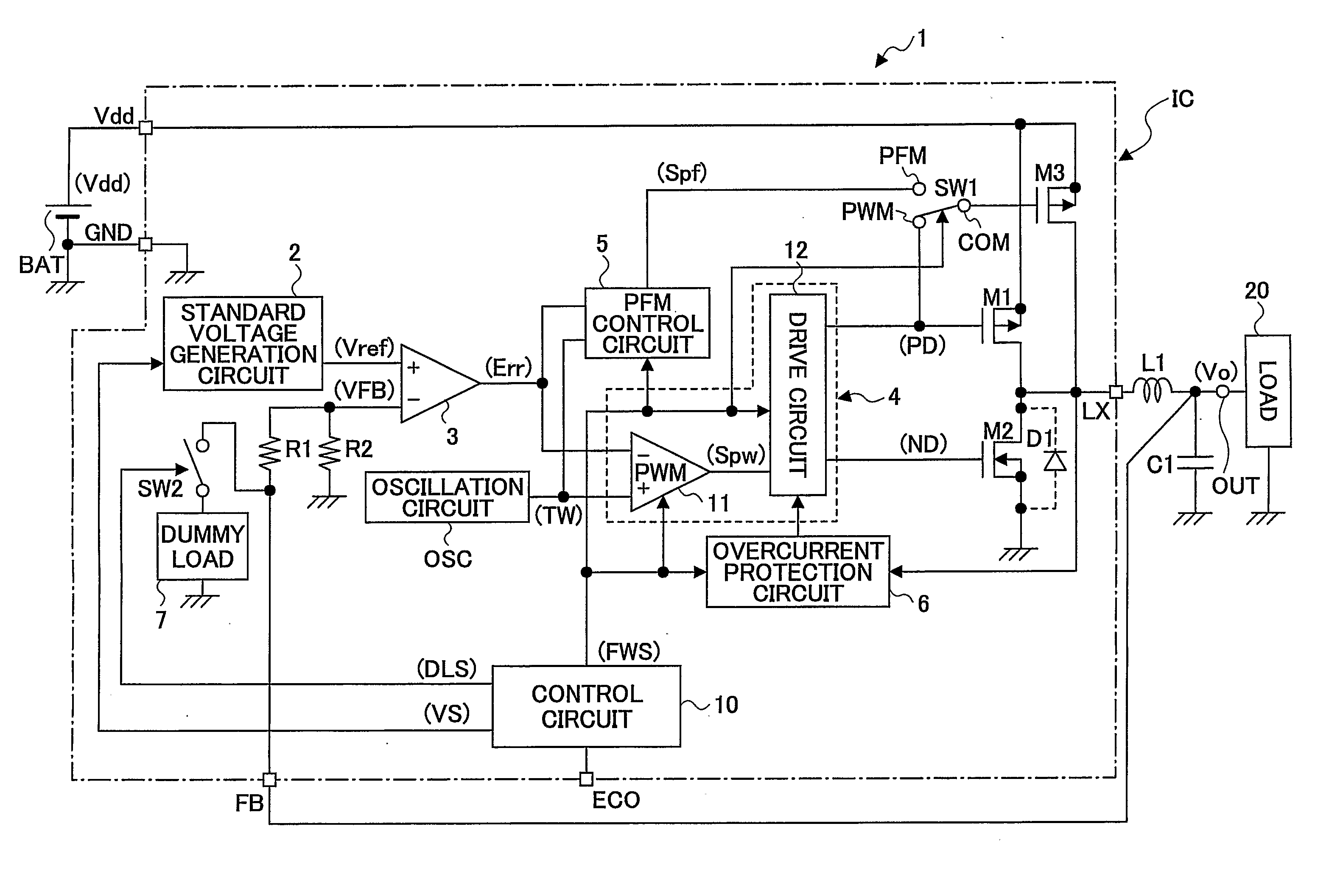
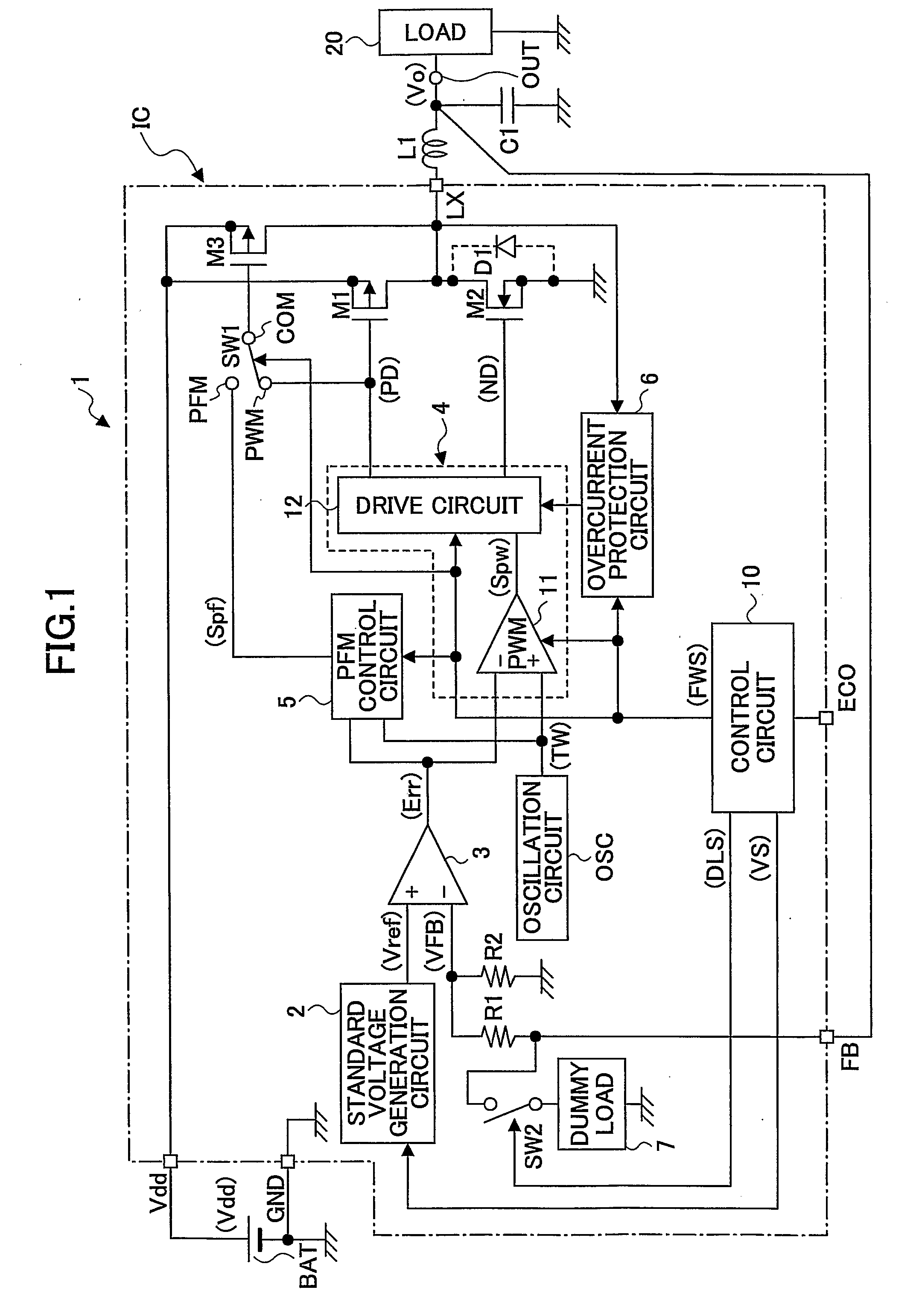
[0025]FIG. 1 is a configuration example of a switching regulator 1 according to the first embodiment of the present invention.

[0026] In FIG. 1, an output voltage variable switching regulator is provided for generating a predetermined voltage from an input voltage Vdd input to the Vdd terminal which is an input terminal from a DC voltage BAT and outputting the predetermined voltage as an output voltage Vo from an output terminal OUT to a load 20.

[0027] The switching regulator 1 includes a first switching element M1 comprising a PMOS transistor performing a switching operation for controlling outputting the input voltage Vdd, another switching element M2 for synchronous rectification comprising an NMOS transistor, an inductor L1 and a condenser C1 comprising a smoothing circuit, and output voltage detecting resistors R1 and R2 for dividing the output voltage Vo so as to generate and output a divided voltage VFB.

[0028] Moreover, the switching regulator 1 further includes a standard ...


PUM


Abstract

A switching regulator converts an input voltage to a predetermined voltage and outputs the predetermined voltage to a load through an output terminal. The switching regulator includes a first switching element, a second switching element, a control switching circuit part, and a smoothing circuit. When a first operating mode in which a PFM control is performed and a voltage from the output terminal becomes a first voltage is shifted to a second operating mode in which a PWM control is performed and the voltage from the output terminal becomes a second voltage larger than the first voltage, the control switching circuit part increases the voltage from the output terminal stepwise progressively from the first voltage to the second voltage while performing the PWM control.

Description

TECHNICAL FIELD [0001] The present invention generally relates to a switching regulator that can change the output voltage used in portable devices, and especially to a switching regulator for lowering an overshoot of the output voltage when increasing the output voltage, and a method for switching the output voltage of the switching regulator. BACKGROUND ART [0002] In recent years, the saving energy has become desirable from the point of view of environmental operations. In devices such as a cell phone, a digital camera and the like wherein a battery is used, reducing the electric power consumed in the devices has become more important from the view of increasing the service life of the battery. For this purpose, as for the power supply circuit, non-insulated step-down type switching regulators with high efficiency and reduced size in which an inductor is used are in wide use (hereinafter, referred to as switching regulators). The switching regulators are highly efficient at rated ...

Claims


Application Information

Patent Timeline
Patent Type & Authority Applications(United States)
IPC IPC(8): G05F1/00
CPCH02M3/156G05F1/10G05F1/40
Inventor KATOH, TOMONARIMATSUO, MASAHIRO
Owner RICOH ELECTRONIC DEVICES CO LTD
Why Eureka
Try Eureka