
Flat panel display device and method thereof

a display device and flat panel technology, applied in the direction of discharge tube luminescnet screens, packaging goods, packaging foodstuffs, etc., can solve the problems of oxidization and corrosion, adversely affecting the display function, and the emission characteristics of organic films

Active Publication Date: 2007-07-12
SAMSUNG DISPLAY CO LTD
View PDF5 Cites 58 Cited by
  • Summary
  • Abstract
  • Description
  • Claims
  • Application Information

AI Technical Summary

Benefits of technology

[0006]The present invention provides a flat panel display device preventing the degradation of performance over a period of time by blocking the permeation of harmful material such as oxygen or moisture.
[0007]The present invention also provides a flat panel display device minimizing an additional process or an additional manufacturing cost.
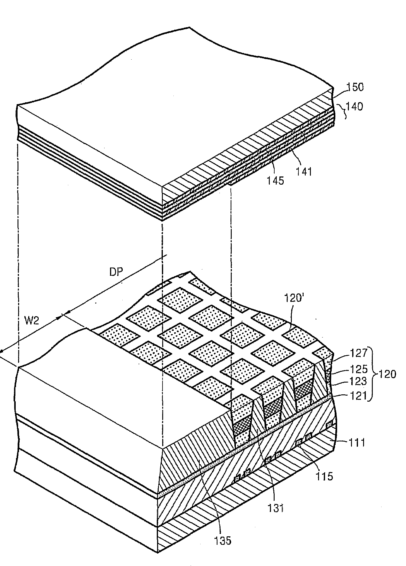
[0013]According to other exemplary embodiments of the present invention, there is provided a method of fabricating a flat panel device having protection from harmful material, the flat panel display device including a display area where an image is displayed and a non-display area located at an outside of the display area, the method including providing a substrate, forming bank portions within the display area on the first substrate in a pattern having partitioned openings to receive emission elements within the openings, and forming dummy bank portions within the non-display area on the first substrate substantially simultaneously with forming the bank portions in the display area, the dummy bank portions forming at least part of a blocking wall preventing entrance of harmful material into the display area from a side of the flat panel device.

Problems solved by technology

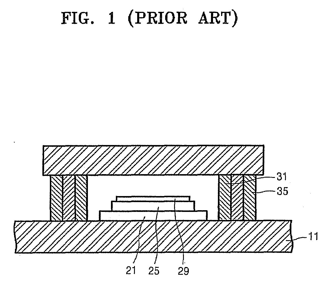
The second electrode layer 29 injecting electrons is highly active and chemically unstable, and therefore reacts easily with moisture and oxygen of the outside air leading to oxidization and corrosion.
With the permeation of moisture or oxygen into the organic film 25, the emission characteristics of the organic film 25 degrade due to a change of crystalline structure and in an extreme case, dark spots are formed, adversely affecting a display function.
In the conventional art, an additional process of forming the surrounding wall is required so that manufacturing productivity is lowered, thereby causing a problem that the reliability of the product is deteriorated such as due to a bad sealing property of the wall.

Method used


Image

  • Flat panel display device and method thereof
  • Flat panel display device and method thereof
  • Flat panel display device and method thereof

Examples


Embodiment Construction

[0025]The invention will now be described more fully hereinafter with reference to the accompanying drawings, in which embodiments of the invention are shown. This invention may, however, be embodied in many different forms and should not be construed as limited to the embodiments set forth herein. Rather, these embodiments are provided so that this disclosure will be thorough and complete, and will fully convey the scope of the invention to those skilled in the art. Like reference numerals refer to like elements throughout.

[0026]It will be understood that when an element is referred to as being “on” another element, it can be directly on the other element or intervening elements may be present there between. In contrast, when an element is referred to as being “directly on” another element, there are no intervening elements present. As used herein, the term “and / or” includes any and all combinations of one or more of the associated listed items.

[0027]It will be understood that, alt...


PUM


Abstract

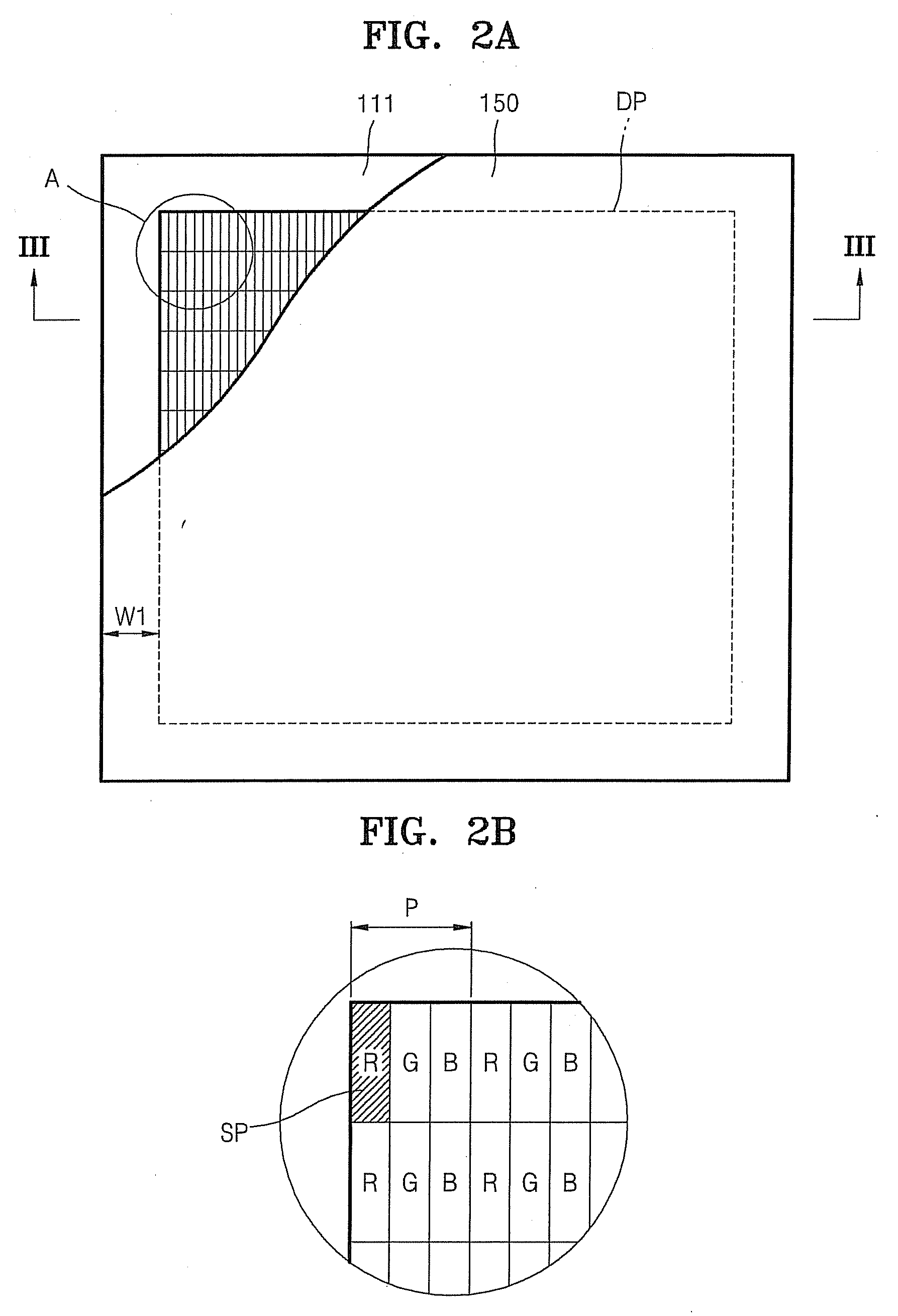
A flat panel display device including a display area where an image is displayed and a non-display area located at an outside of the display area includes bank portions arranged in a pattern in the display area and partitioning a plurality of openings, emission elements located in the openings, dummy bank portions formed in the non-display area and integrated therewith, and a sealing passivation layer having a multi-layered structure of organic films and inorganic films alternately arranged, one organic film being located at an interface directly contacting the emission element and one inorganic film located firstly on an outermost portion of the dummy bank portions when the sealing passivation layer extends from the display area to the non-display area.

Description

[0001]This application claims priority to Korean Patent Application No. 10-2006-0003119, filed on Jan. 11, 2006 and all the benefits accruing therefrom under 35 U.S.C. §119, and the contents of which in its entirety are herein incorporated by reference.BACKGROUND OF THE INVENTION[0002]1. Field of the Invention[0003]The present invention relates to a flat panel display device and method thereof, and more particularly, to a flat panel display device preventing oxidation / corrosion due to harmful material such as oxygen / moisture and a method of fabricating the flat panel display device.[0004]2. Description of the Related Art[0005]FIG. 1 is a cross-sectional view of a conventional flat panel display device and in particular, an organic light-emitting display device disclosed in Japanese Patent Publication No. 1999-121165. Referring to FIG. 1, on a substrate 11, a first electrode layer 21 constituting an anode electrode injecting holes, an organic film 25 in which light is emitted by the ...

Claims


Application Information

Patent Timeline
Patent Type & Authority Applications(United States)
IPC IPC(8): H05B33/04H01L51/50H05B33/10
CPCH01L27/3223H01L27/3246H05B33/04H01L51/5256H01L51/5246H10K59/88H10K59/122H10K59/8731H10K59/8722A45D44/18A46B15/0091A46B15/0069A46B15/0055A46B9/04A61C19/02A61C15/00A46B17/04A46B2200/108H10K50/8426H10K50/8445
Inventor OH, TAE-SIKKANG, SUNG-KEEKIM, JUNG-WOOLEE, HO-NYEONCHUN, YOUNG-TEASONG, MI-JEONG
Owner SAMSUNG DISPLAY CO LTD
Learn More