Pumping tower support system and method of use

a technology of support system and floor, which is applied in the direction of girders, building scaffolds, transportation and packaging, etc., can solve the problems of unreasonably high cost, labor-intensive and time-consuming both methods, and complex arrangements

Active Publication Date: 2007-07-12
PUTZMEISTER AMERICA
View PDF30 Cites 21 Cited by
  • Summary
  • Abstract
  • Description
  • Claims
  • Application Information

AI Technical Summary

Benefits of technology

[0007] The present invention relates to a support system for supportably securing a vertically movable support structure to a floor structure of a building. The support structure extends through an opening formed in the floor structure. The support system includes a set of support brackets pivotably mounted relative to vertical support members of the support structure. The support brackets are supportably engageable with a portion of the support structure and a first floor structure in a first supporting position. The support brackets are freely swingable and movably engageable with a second floor structure as the support structure is moved relative to the second floor structure enabling the support brackets to be supportably engageable with the portion of the support structure and the second floor structure in a second supporting position.

Problems solved by technology

Both methods are labor intensive and time consuming, and are known to be user-unfriendly involving a great deal of worker manipulation while operating with a tower crane and inexact openings.
However, these arrangements are generally complex in nature and can be unreasonably expensive.

Method used


Image

  • Pumping tower support system and method of use
  • Pumping tower support system and method of use
  • Pumping tower support system and method of use

Examples


Embodiment Construction

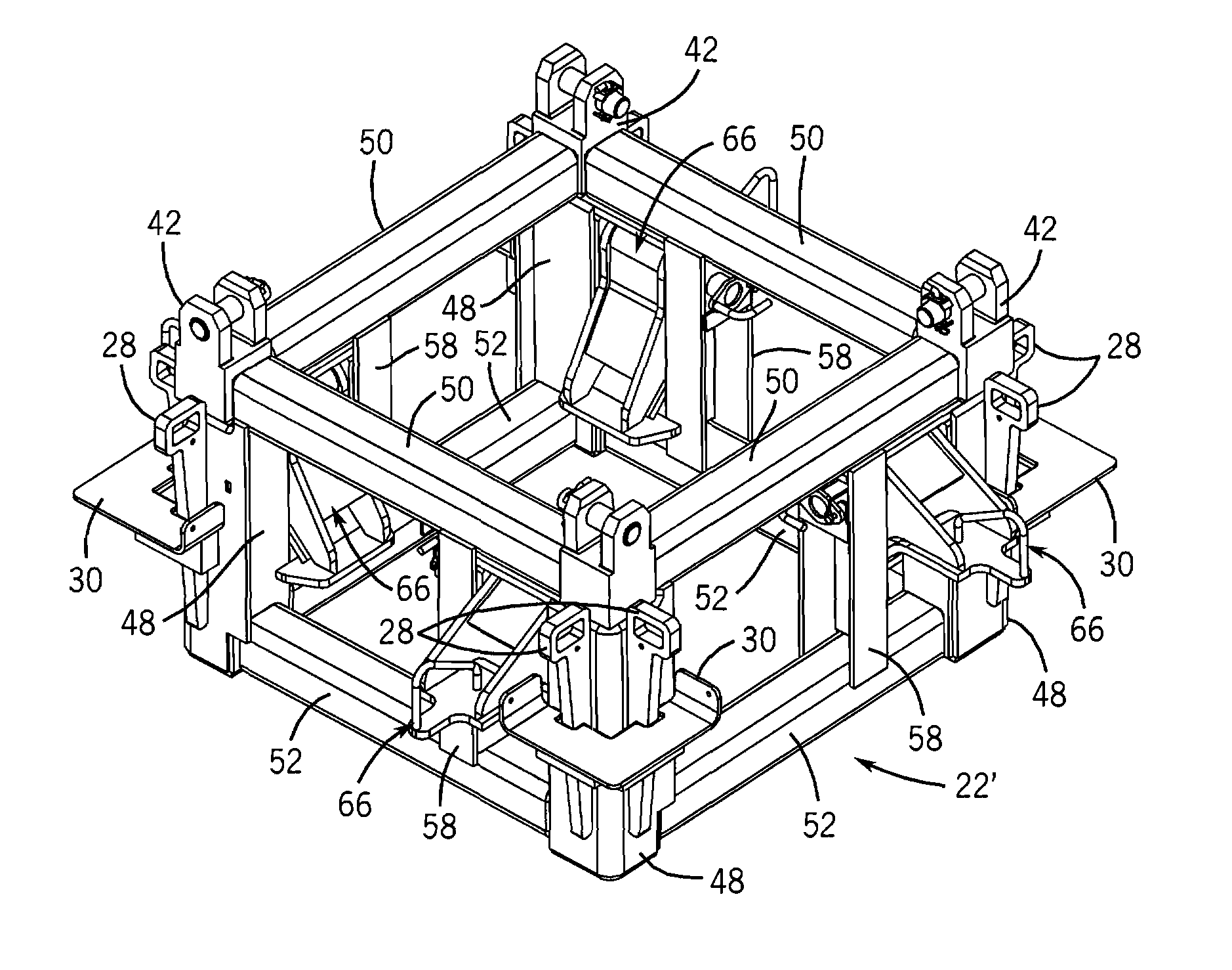
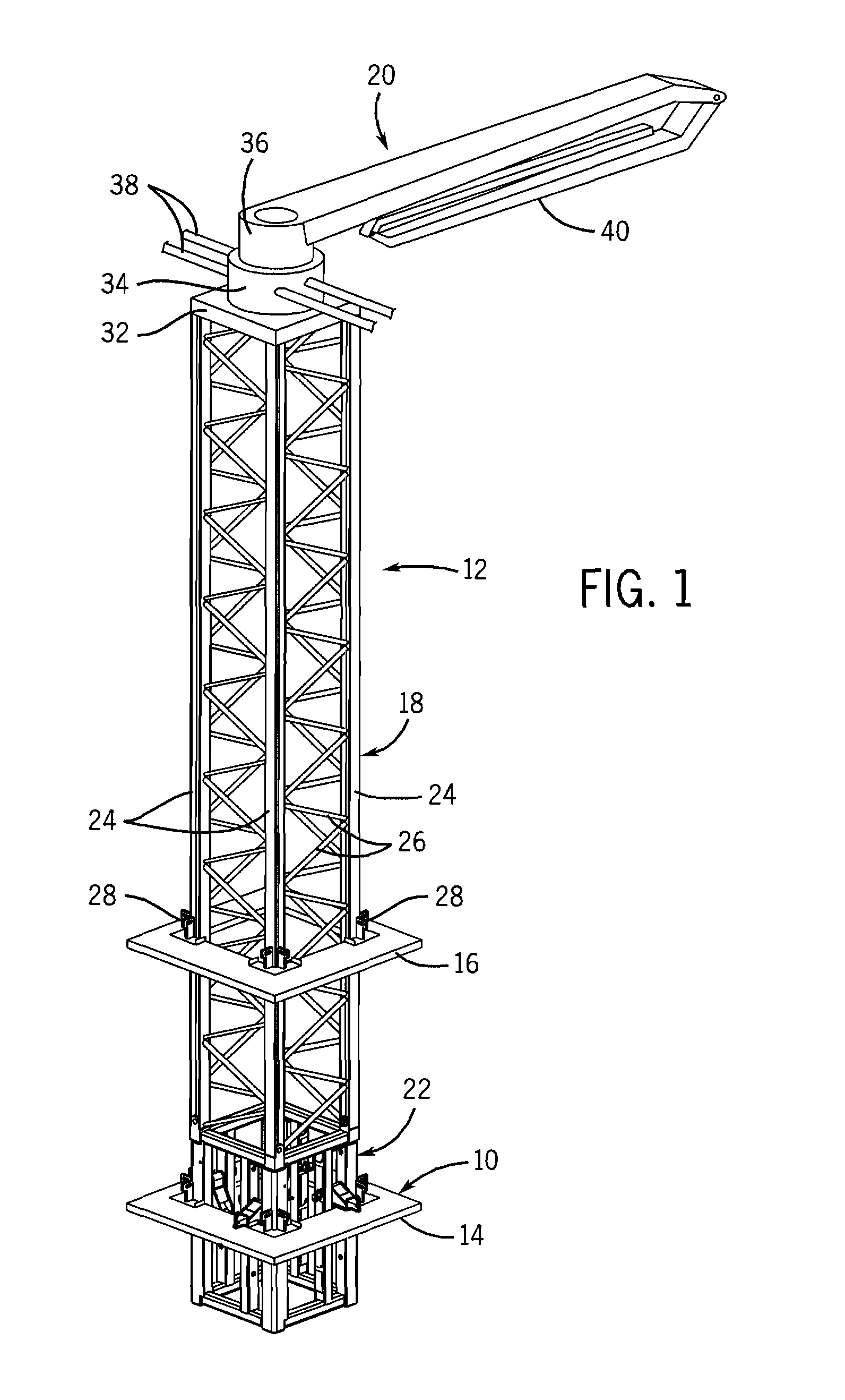
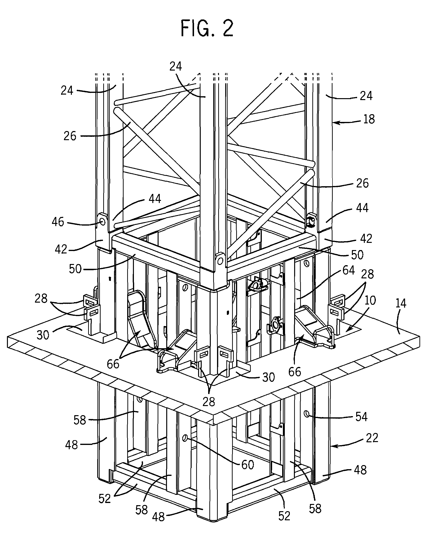
[0022]FIGS. 1 and 2 illustrate a tower-to-floor support system 10 for supportably coupling a vertically movable support structure or pumping tower 12 to a floor structure 14 of a building under construction. As is known, the pumping tower 12 passes through an opening 15 (FIG. 4) in the floor structure 14 at a first or ground level, and extends upwardly through aligned openings 15 in subsequently completed upper floor structures such as shown at 16. As construction of the building progresses and new floor structures are added, the entire pumping tower 12 must be raised by a lifting device or jumped upwardly by a climbing system and secured to an upper floor structure 16 by means of the support system 10 embodying the present invention.

[0023] The pumping tower 12 includes a lattice tower 18 formed from one or more joined sections having a concrete placing boom 20 rotatably attached at an upper end, and a base or support framework 22 fixedly attached to the lower end. It should be und...


PUM

PropertyMeasurementUnit
rotationaaaaaaaaaa
timeaaaaaaaaaa
movementaaaaaaaaaa

Abstract

A support system is provided for supportably securing a vertically movable support structure having a boom attached thereto to a floor structure of a building. The support structure extends through an opening formed in the floor structure. The support system includes a set of support brackets pivotably mounted relative to vertical support members of the support structure. The support brackets are supportably engageable with a portion of the support structure and a first floor structure in a first supporting position. The support brackets are freely swingable and movably engageable with a second floor structure as the support structure is moved relative to the second floor structure enabling the support brackets to be supportably engageable with the portion of the support structure and the second floor structure in a second supporting position.

Description

CROSS-REFERENCE TO RELATED APPLICATION [0001] This application relates to and claims priority from U.S. Provisional Patent Application Ser. No. 60 / 758,472 filed Jan. 12, 2006.FIELD OF THE INVENTION [0002] The present invention relates generally to a tower-to-floor support system that more effectively allows a vertically movable tower-supported concrete placing boom to be supported at different vertical positions relative to the floor structure development of a building under construction. BACKGROUND OF THE INVENTION [0003] Currently, concrete placing booms are used at large work sites such as the construction of a multi-floored building for placing concrete in hard to access locations. Typically, the concrete placing boom is removably mounted to a support structure, such as a pumping tower, that passes through the developing floor structure of a building, and extends above a working surface such that concrete can be supplied from above. The concrete placing boom can be removed from ...

Claims


Application Information

Patent Timeline
Patent Type & Authority Applications(United States)
IPC IPC(8): E04H12/18
CPCB60K15/01B60K2015/03118B66C23/286Y10T29/49966E04G21/04F16L13/0209E04G21/0427B66C23/32Y10T137/0441Y10T137/86372Y10T137/6881
Inventor KNIGGE, WALTER N.CARBEAU, C. WILLIAM
Owner PUTZMEISTER AMERICA
Why Eureka
Try Eureka