
System and method for selectively energizing catheter electrodes

a technology of electrodes and selective energization, which is applied in the field of catheters for electric diagnosis and treatment of the heart, can solve the problems of cardiac arrhythmias, dispersion of rf energy in the blood, fouling of the tip electrode, etc., and achieve the effect of improving energy efficiency and improving ablation capabilities

Active Publication Date: 2007-07-05
BIOSENSE WEBSTER INC
View PDF27 Cites 58 Cited by
  • Summary
  • Abstract
  • Description
  • Claims
  • Application Information

AI Technical Summary

Benefits of technology

[0010] The present invention is directed to a system, a method and a catheter that provide improved ablation capabilities and improved energy efficiency by selectively energizing catheter electrodes on the basis of impedance measurements. In particular, the invention is directed to the selective energization of catheter radial electrodes that together with a tip electrode form a generally continuous tissue contact surface, wherein the selection is made on the basis of impedance measurement as an indication of the amount of tissue contact of each radial electrode.

Problems solved by technology

Cardiac arrhythmias, the most common of which is ventricular tachycardia (VT), are a leading cause of death.
Absence of contact or poor contact of the tip electrode with the heart wall leads to dissipation of the RF energy in the blood, as well as possible fouling of the tip electrode with the concomitant possibility of blood clot formation.
A disadvantage of typical ablation electrodes is that it is sometimes difficult to accurately predict lesion size because the lesion size can vary depending on the orientation of the ablation electrode.
The size of the lesion is often related to the amount surface area in contact with the tissue and there can be significant energy loss through the portion of the electrode not in contact with any tissue, particularly since blood has a higher conductivity than tissue.
Moreover, overheating of the tip electrode can cause complications, including the formation of char andlor thrombus on the electrode surface.
The creation of char and thrombus is unsafe, as the char and thrombus can be dislodged from the electrode during the procedure or during removal of the catheter after the procedure.

Method used


Image

  • System and method for selectively energizing catheter electrodes
  • System and method for selectively energizing catheter electrodes
  • System and method for selectively energizing catheter electrodes

Examples


Embodiment Construction

[0027] The present invention provides a system and method and a catheter for use therewith that ablates with improved energy efficiency. The invention is directed to the selective energization of catheter radial electrodes that together with a tip electrode form a generally continuous tissue contact surface, wherein the selection is made on the basis of impedance measurement as an indication of the amount of tissue contact of each radial electrode.

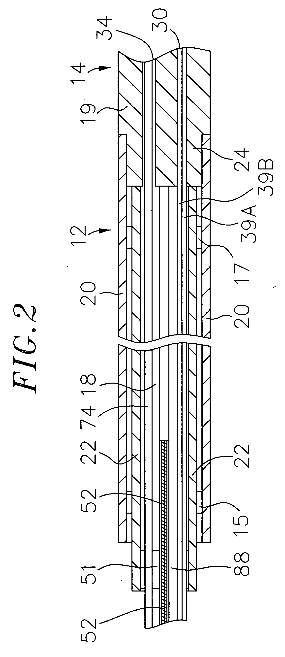
[0028] With reference to FIG. 1, the catheter 10 comprises an elongated catheter body 12 having proximal and distal ends, an intermediate section 14 at the distal end of the catheter body, a control handle 16 at the proximal end of the catheter body, and an irrigated tip section 26 at the distal end of the catheter body. The tip section carries a tip electrode 28 and a plurality of radial electrodes 37 immediately proximal the tip electrode. The tip section 26 of the catheter may also carry an electromagnetic location sensor 72 to determi...


PUM


Abstract

The present invention is directed to a system, a method and a catheter that provide improved ablation capabilities and improved energy efficiency by selectively energizing catheter electrodes on the basis of impedance measurements. In particular, the invention is directed to the selective energization of catheter radial electrodes that together with a tip electrode form a generally continuous tissue contact surface, wherein the selection is made on the basis of impedance measurement as an indication of the amount of tissue contact of each radial electrode.

Description

FIELD OF THE INVENTION [0001] The present invention is directed to a catheter for electric diagnosis and treatment of the heart, and more particularly to a catheter for mapping and ablation. BACKGROUND OF THE INVENTION [0002] Cardiac arrhythmias, the most common of which is ventricular tachycardia (VT), are a leading cause of death. In a majority of patients, VT originates from a 1 mm to 2 mm lesion located close to the inner surface of the heart chamber. One of the treatments for VT comprises mapping the electrical pathways of the heart to locate the lesion followed by ablation of the active site. [0003] U.S. Pat. No. 5,546,951; U.S. patent application Ser. No. 08 / 793,371; and PCT application WO 96 / 05768, which are incorporated herein in their entirety by reference, disclose methods for sensing an electrical property of heart tissue such as local activation time as a function of the precise location within the heart. The data are acquired by advancing into the heart one or more cat...

Claims


Application Information

Patent Timeline
Patent Type & Authority Applications(United States)
IPC IPC(8): A61B18/18A61B18/14A61B5/296
CPCA61B18/1206A61B18/1492A61B2017/00026A61B2018/00029A61B2018/1467A61B2018/124A61B2019/5251A61B2018/00351A61B2018/00577A61B2018/00875A61B2034/2051A61B18/1233A61B2018/00988A61B34/20A61B2018/00642A61B2018/00702A61B2018/00904A61M25/005A61M25/0147
Inventor JIMENEZ, EDUARDO
Owner BIOSENSE WEBSTER INC
Learn More