Data transmission method and arrangement

a data transmission and data technology, applied in the field of data transmission methods and arrangements, can solve the problems of insufficient use of user-specific antenna beams, varies in the number of those needing radio resources, and costs during planning and implementation phases, and achieves better isolation and lower side-lobe levels

Inactive Publication Date: 2007-07-05
NOKIA SOLUTIONS & NETWORKS OY
View PDF14 Cites 5 Cited by
  • Summary
  • Abstract
  • Description
  • Claims
  • Application Information

AI Technical Summary

Benefits of technology

[0019] The method and system of the invention provide a plurality of advantages. By employing the method of the invention, a desired power balance between different antenna elements of an antenna array is achieved without having to make too narrow antenna beams. The method provides a better isolation between different cells, which means lower side-lobe levels. In addition, the system allows inaccuracies in the weight factor determination, which means that it is not too sensitive to phase changes: it is even possible to have an inaccuracy of 5 degrees in the phase. The method also allows the formation of several radio cells by using the same antenna beam.

Problems solved by technology

However, it is not always sufficient that a user-specific antenna beam is used for monitoring the location of the user as precisely as possible.
Namely, the problem is that the number of those needing radio resources varies in the coverage area.
A problem with fixed-beam systems is, however, how to design power amplifiers, because, in the worst case, each power amplifier of an antenna array has different designs, which causes costs during planning and implementation phases.
In digital beam forming, the problem with an attempt to have a power balance between different antenna elements is that compromises have to be made in order to optimize the width and side-lobe levels of antenna beams.

Method used


Image

  • Data transmission method and arrangement
  • Data transmission method and arrangement
  • Data transmission method and arrangement

Examples


Embodiment Construction

[0029] The solution according to the invention is particularly applicable to a CDMA radio system using a direct sequence technique. Other applications may include satellite systems, military telecommunication systems and private non-cellular networks. However, the solution of the invention is not restricted to them.

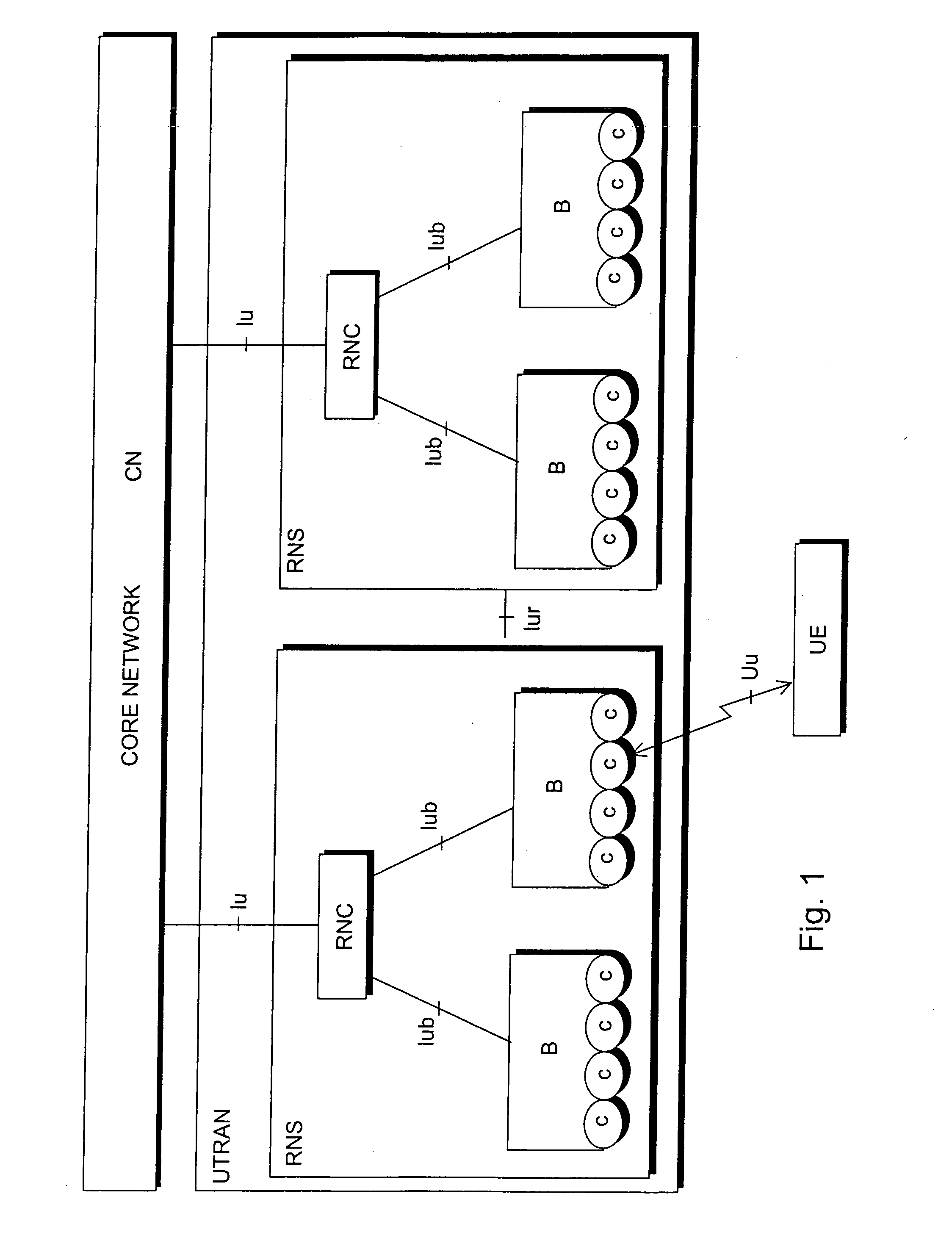
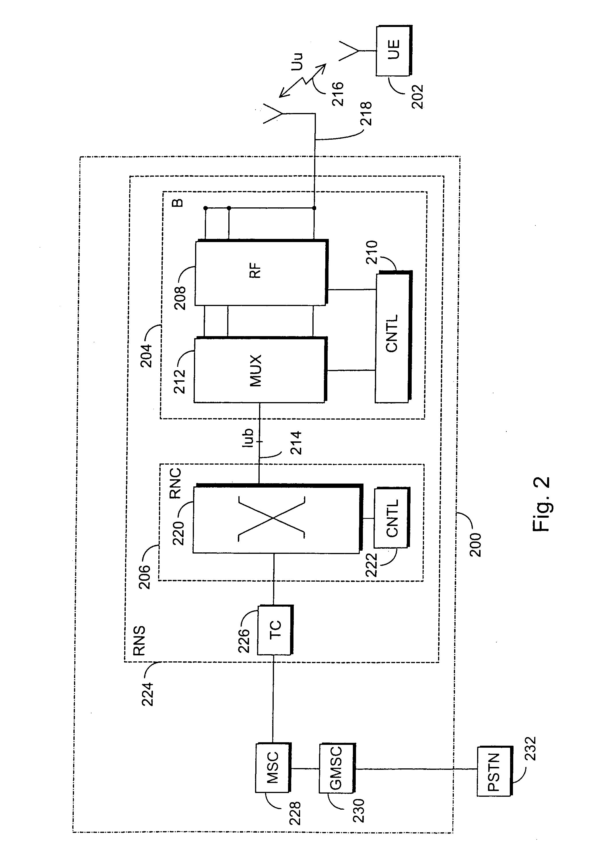
[0030] With reference to FIG. 1, the structure of a mobile telephone system is explained by way of example. The main parts of the mobile telephone system are core network CN, universal terrestrial radio access network of the mobile telephone system UTRAN and user equipment UE. The interface between the CN and the UTRAN is called Iu and the air interface between the UTRAN and the UE is called Uu.

[0031] The UTRAN comprises radio network subsystems RNS. The interface between the RNSs is called Iur. The RNS comprises a radio network controller RNC and one or more nodes B. The interface between the RNC and B is called Iub. The coverage area, or cell, of the node B is marked ...


PUM


Abstract

A method for determining weight factors of antenna beams, the method comprising using at least one directional antenna beam implemented with an antenna array to establish a radio link, forming a radio cell with the antenna beam, dividing the radio cell into at least two different cells by dividing the antenna beam, selecting weight factors of antenna elements of the antenna array such that the antenna element specific sums of weight factors of a radio cell formed with the antenna array and corresponding weight factors of at least one, second radio cell formed with the same antenna array are at least substantially equal within predetermined limits in order to achieve a predetermined power balance between different antenna elements. (FIG. 7)

Description

[0001] This application is a continuation of U.S. patent application Ser. No. 10 / 712,255, filed Nov. 14, 2003, which is a continuation application of international application PCT / FI01 / 00471 filed May 15, 2001 which designated the U.S. and was published under PCT article 21(2) in English.FIELD OF THE INVENTION [0002] The invention relates to a method and an arrangement for determining weight factors of directional antenna beams. To establish a radio link, the method employs at least one directional antenna beam implemented with an antenna array. BACKGROUND OF THE INVENTION [0003] When adaptive antenna arrays are used, the basic principle is that radiation beams are narrow and they are directed as directly as possible at a desired receiver. Widely known methods of using adaptive antenna arrays can be divided into two main groups: radiation beams are directed at a receiver, or the most suitable beam is selected from various alternative beams. For a downlink transmission, a suitable be...

Claims


Application Information

Patent Timeline
Patent Type & Authority Applications(United States)
IPC IPC(8): H04B1/00H04B15/00H01Q3/26H04B7/005H04B7/02H04B7/06
CPCH01Q3/26H04B7/0452H04W52/42H04W52/346H04B7/0617
Inventor YLITALO, JUHA
Owner NOKIA SOLUTIONS & NETWORKS OY
Why Eureka
Try Eureka