
Metallic local reinforcement for heavy loaded joints of composite components

a local reinforcement and composite component technology, applied in the direction of transportation and packaging, mechanical equipment, other domestic objects, etc., can solve the problems of not being able to use hybrid materials as local reinforcement in heavy-load lap joints, unable to meet the requirements of surface treatment, and not being able to meet the requirements of high-level volatile organic compounds (voc), so as to improve the performance of carbon composite joints, reduce the structural weight and thickness of bolted joints, and reduce the effect of weight and thickness

Inactive Publication Date: 2007-07-05
AIRBUS OPERATIONS SL
View PDF3 Cites 11 Cited by
  • Summary
  • Abstract
  • Description
  • Claims
  • Application Information

AI Technical Summary

Benefits of technology

[0013] The present invention embodies in particular a new application of metal on full composite parts as local reinforcement to reduce bolted joint structural weight and thickness for permanent or detachable joints. Internal Airbus España research has demonstrated that, on heavy loaded bolted joints, interleaving one or more foils, sheets or plates of metal, particularly titanium, into the composite part allow a local optimisation. The advantage is encountered whether the case is single or double lap shear joints, lugs or other fixing architectures. Such optimisation is traduced onto weight and thickness reduction of the joint, with subsequent eccentricity decrease what improves carbon composite joint performance.
[0014] A basic characteristic of this invention is that carbon plies coming from the full-composite area are not interrupted along the reinforcement, ensuring a proper load transfer. Ti foils replace most or all additional CFRP lamina that would have been necessary to strengthen and thicken up the bolted joint on a full CFRP joint whether permanent or detachable as it is usual in aircraft architectures. Eventually, depending on the detailed design, some additional composite plies could be needed in addition to the Ti foils or plates.

Problems solved by technology

A common issue with all fibre / metal materials is the required surface treatment to be applied to the metal to ensure a proper bonding to the composite or to the adhesive layer if exists.
With new regulations, old and complex pollutant methods containing high levels of Volatile Organic Compounds (VOC) are no longer allowed.
However hybrid materials have not been used as local reinforcement in heavy loaded lap joints on aircraft primary structures made of composite materials.

Method used


Image

  • Metallic local reinforcement for heavy loaded joints of composite components
  • Metallic local reinforcement for heavy loaded joints of composite components
  • Metallic local reinforcement for heavy loaded joints of composite components

Examples


Embodiment Construction

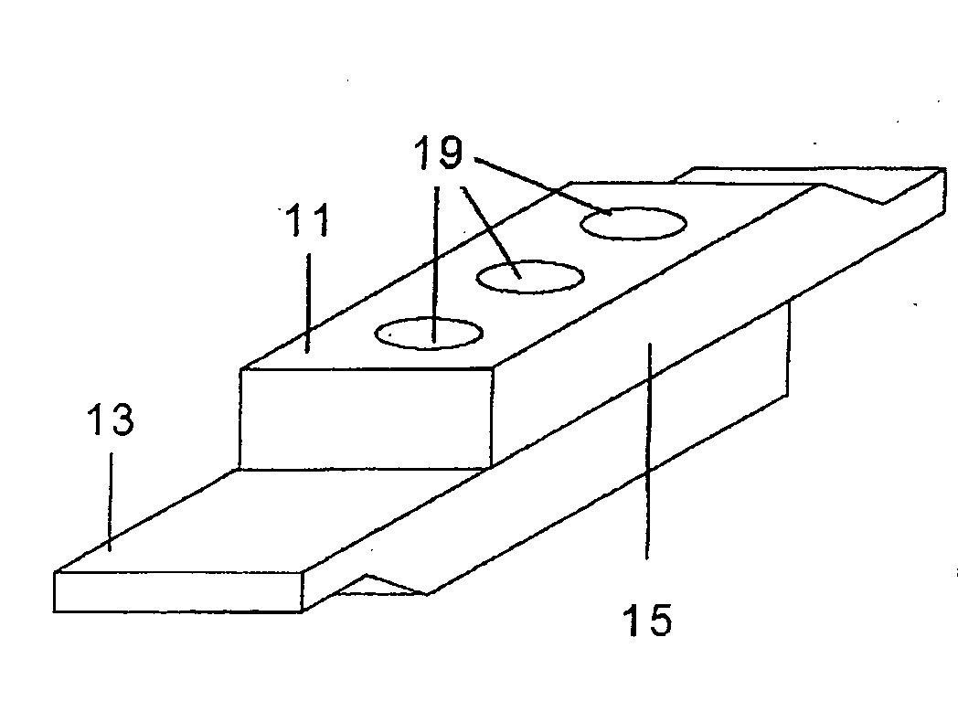
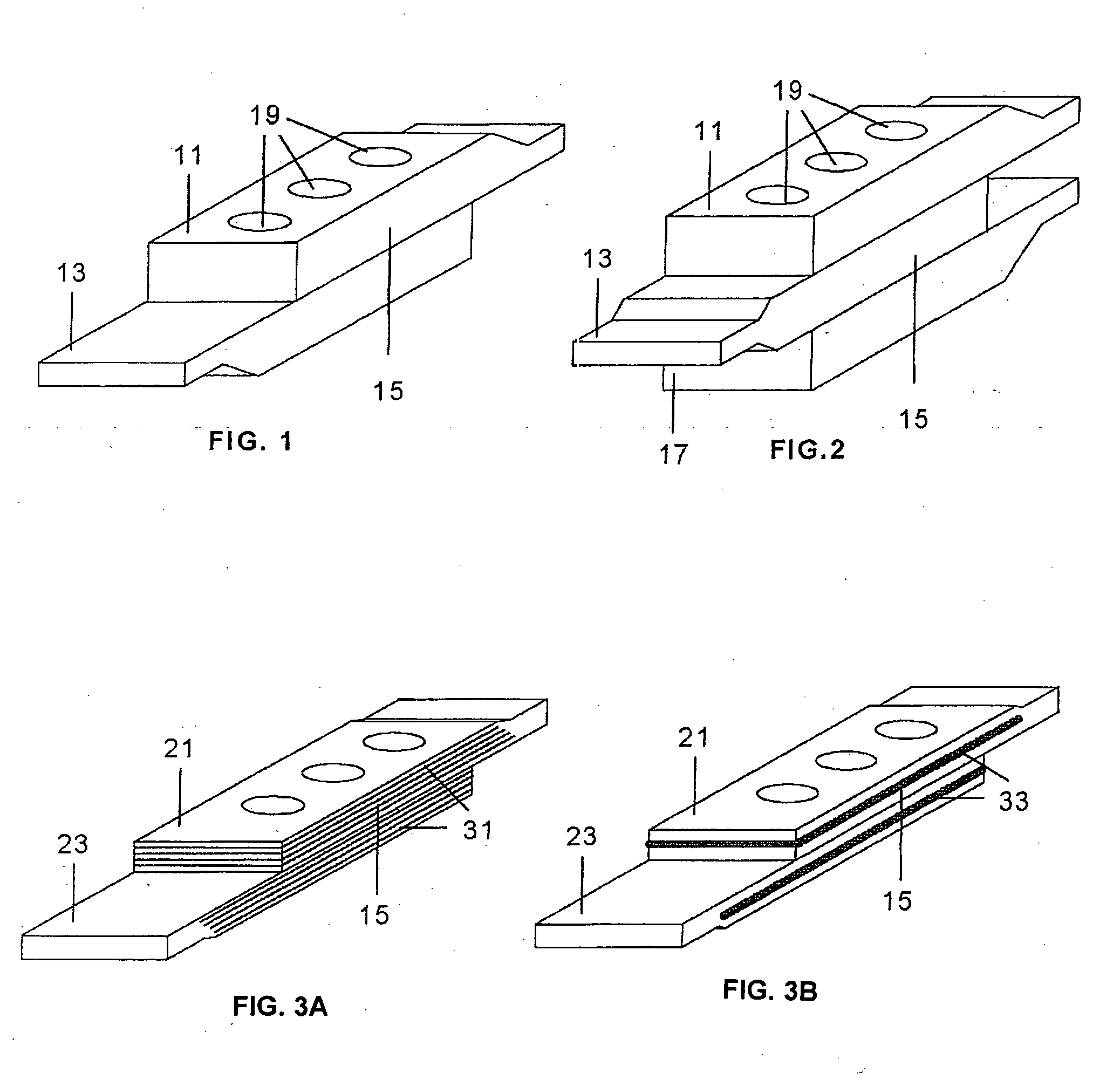
[0023] In known heavy loaded joints between two composite parts 11, 13 (see FIG. 1) both parts 11, 13 are thickened in the joint area 15 with additional plies until the required strength is achieved resulting in a reinforced joint area 15.

[0024] Similarly in heavy loaded joints between three composite parts 11, 13, 17 (see FIG. 2) the three parts 11, 13, 17 are thickened in the joint area 15 with additional plies until the required strength is achieved resulting in a reinforced joint area 15.

[0025] In both cases fastening means such as bolts (not shown) will be used through holes 19 drilled in each part 11, 13, 17 in the zones to be joined.

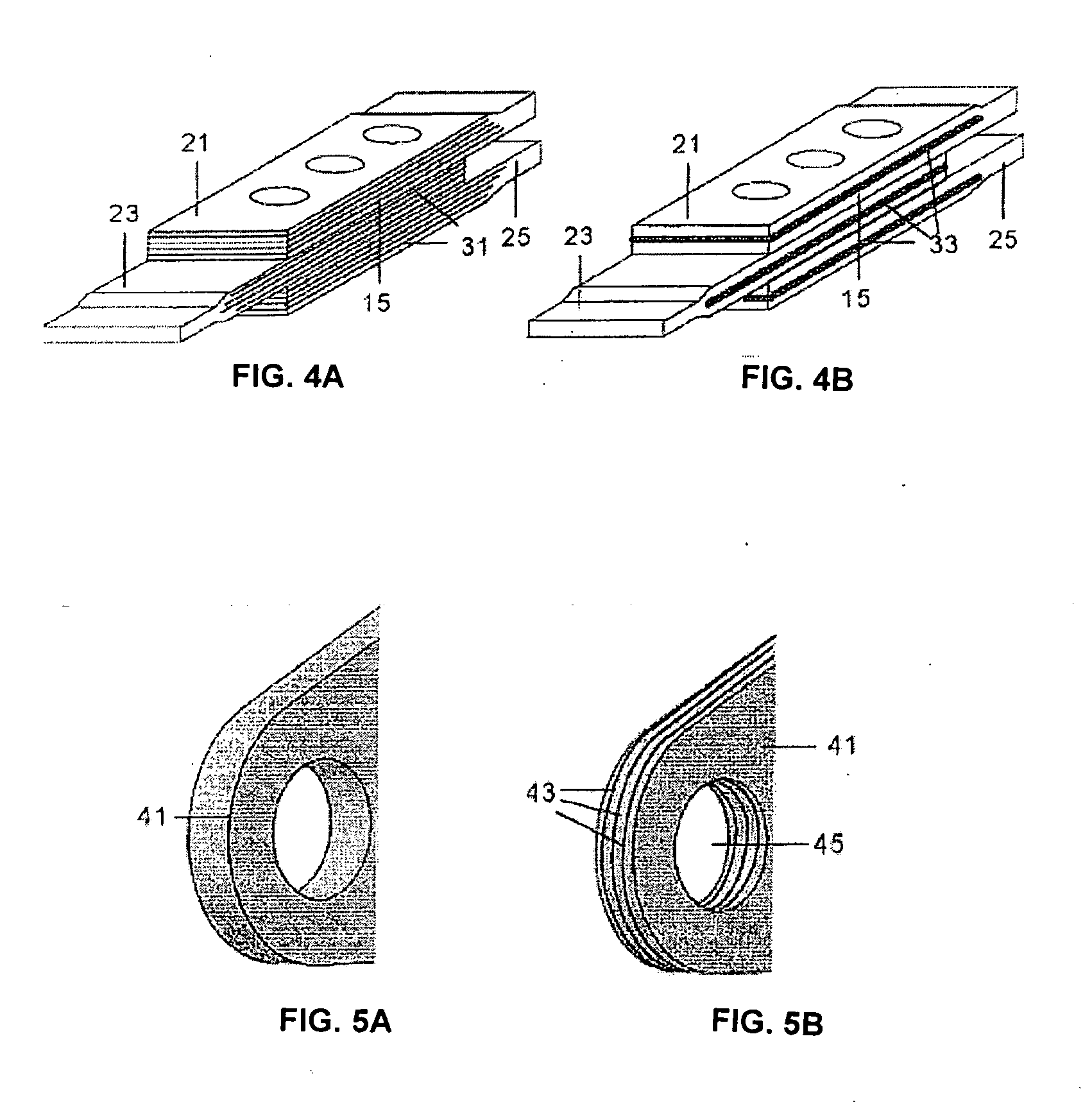
[0026] In a preferred embodiment of the invention shown in FIGS. 3a and 4a, all parts 21, 23; 21, 23, 25 been joined have titanium foils 31 interleaved as reinforcement into the carbon fibre laminates.

[0027] In another preferred embodiment of the invention shown in FIGS. 3b and 4b, all parts 21, 23; 21, 23, 25 have one titanium plate 33 embedd...


PUM

PropertyMeasurementUnit
Fractionaaaaaaaaaa
Fractionaaaaaaaaaa
Fractionaaaaaaaaaa

Abstract

A mechanically fastened permanent or detachable joint between two or more parts (21, 23, 25, 41), at least one of them made of a composite material, preferably carbon fibres impregnated with thermoset resin, with continuous plies from the full-composite area along the joint area (15) and including a metal reinforcement, preferably made of titanium, in the joint area (15), the joint area (15) thickness being increased in the thickness of said reinforcement plus the eventual additional composite plies laid only on the reinforced area. The metal reinforcement may consist of one or more metal foils or sheets (31) interleaved between the composite plies or one or more metal plates (33) embedded between two of the composite plies.

Description

FIELD OF THE INVENTION [0001] The present invention refers to a structural concept of hybrid joint consisting of metallic foils, sheets or plates locally embedded into a composite part. [0002] A preferred application of the hybrid reinforcement is to strengthen heavy loaded bolted joints, fittings or other complex three-dimensional parts of an aircraft. BACKGROUND OF THE INVENTION [0003] Modern history of hybrid Fibre / Metal materials starts on the early eighties: Delft University of Technology introduced ARALL (an Aramid / Aluminium Fibre Metal Laminate—FML—) in 1981. Later, Delft-TU together with Fokker Aerospace developed GLARE (Glass Fibre / Aluminium FML), solving structural limitations that prevented a wide use of ARALL. This has been shown with the introduction of GLARE as replacement of monolithic aluminium on some parts of the largest passenger aircraft program, the A380, in 2001. [0004] For other applications, different combinations of materials could be more suitable. In this ...

Claims


Application Information

Patent Timeline
IPC IPC(8): B32B3/06
CPCB29C66/1122Y10T428/24752B29C66/721B29K2307/00B29L2031/3076B32B15/08F16B5/02B29L2031/737B29C65/562B29C65/601B29C66/7212B29C66/43Y10T428/24017Y10T428/19Y10T428/24008B29C66/73941B29C66/7394B29C66/73921B29C66/7392B29K2305/00B29K2307/04B29K2309/08B29K2277/10B29K2307/02B29K2305/02B29K2305/12B29C66/72141B29L2031/3082B32B2305/08B32B15/14B32B2311/18B32B2262/106B32B15/043B32B2260/021
Inventor ESCOBAR BENAVIDES, FRANCISCO DE PAULACLARET VIROS, DANIELAVILA DOMINGUEZ, RAFAEL
Owner AIRBUS OPERATIONS SL
Learn More