Eureka AIR delivers breakthrough ideas for toughest innovation challenges, trusted by R&D personnel around the world.

Sensor array for detecting the movement of a positioning element moved back and forth using an actuator

a technology of positioning elements and sensors, applied in the field of actuators, can solve the problems that the measurement of movements derived from current and voltage curves at the coils of electromagnets is no longer sufficient, and achieve the effect of increasing the conductor cross section and specific electric resistan

Inactive Publication Date: 2007-07-05
FEV MOTORENTECHN GMBH
View PDF2 Cites 13 Cited by
  • Summary
  • Abstract
  • Description
  • Claims
  • Application Information

AI Technical Summary

Benefits of technology

"The invention is a sensor assembly that is shorter and generates a linear displacement signal. It features a sensor arrangement with a stationary coil arrangement and an axially movable rod-shaped sensor part that is connected to a positioning element. The sensor assembly has a short-circuit element with a final edge that is enclosed by the active coil and at least one passive coil in a final position. The short-circuit element has a linearization effect on the measuring signal by changing the length of penetration into the active coil. The sensor assembly is suitable for detecting the movement of a movable member, particularly a gas exchange valve of a reciprocating internal combustion engine. The invention provides a solution for detecting position with high accuracy and at a high speed."

Problems solved by technology

In view of stricter requirements regarding control accuracy, particularly with respect to influencing the impact velocity of the armature on the pole face of the respective attracting magnet and therefore also the touch-down speed of the gas exchange valve on the valve seat, a measurement of movements derived from the current and voltage curves at the coils of the electromagnets no longer appears sufficient because the signals obtained therefrom can only be used for the subsequent engine cycle.

Method used


Image

  • Sensor array for detecting the movement of a positioning element moved back and forth using an actuator
  • Sensor array for detecting the movement of a positioning element moved back and forth using an actuator
  • Sensor array for detecting the movement of a positioning element moved back and forth using an actuator

Examples


Embodiment Construction

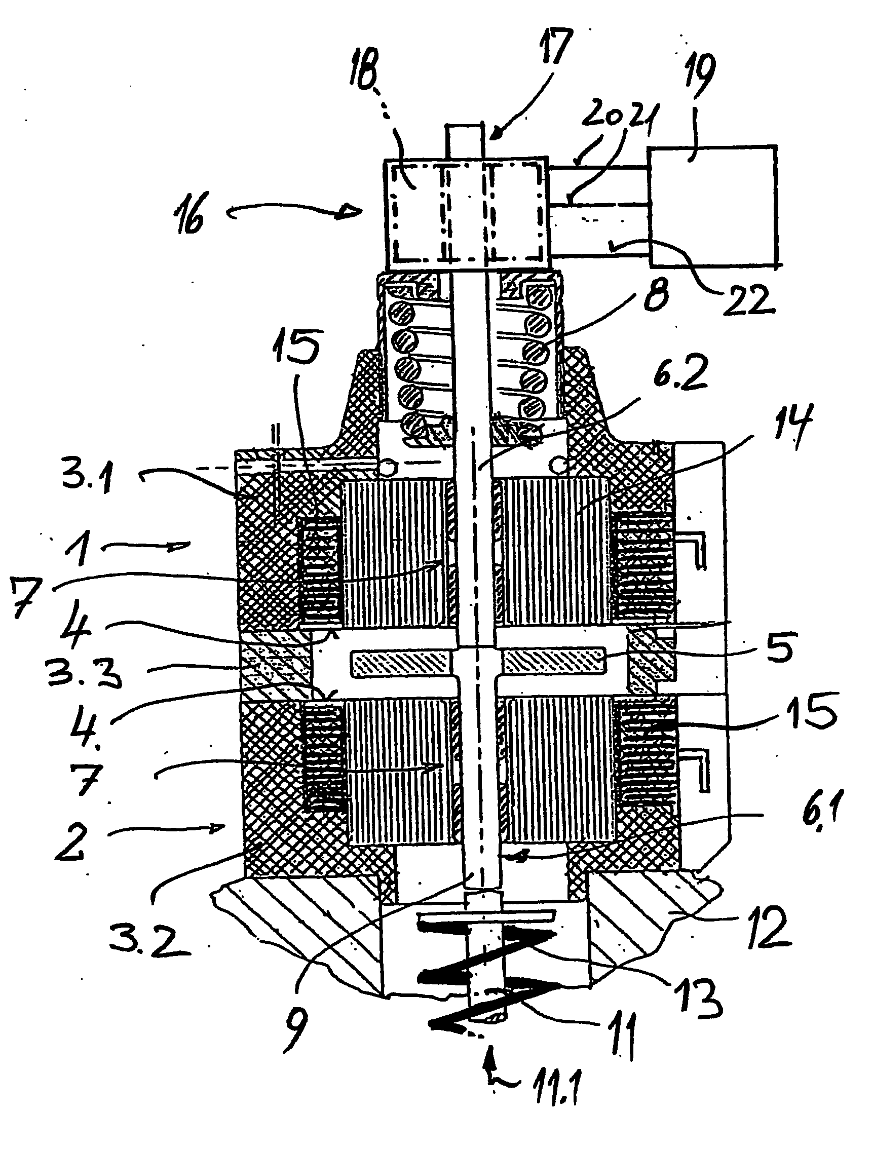
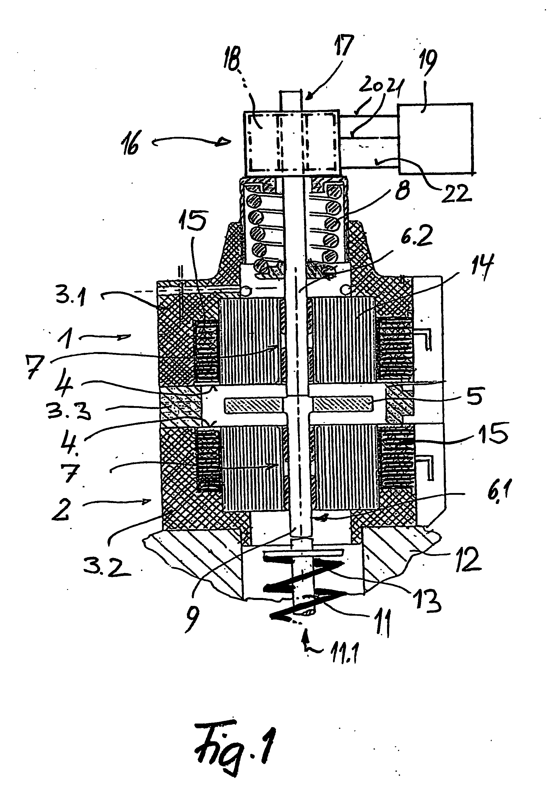
[0029] The electromagnetic actuator shown in FIG. 1 is essentially formed by two electromagnets 1 and 2 that are enclosed by two housing parts 3.1 and 3.27 wherein these two housing parts are spaced apart from one another by means of a housing part 3.3 in the form of a spacer, and are positioned such that their pole faces 4 point toward one another. An armature 5 is arranged in the space enclosed by the spacer 3.3 between the two poles faces 4, and is guided in a guide 7 by means of a guide pin 6.1 such that it can be moved back and forth.

[0030] The armature 5 is connected to a return spring 8 by means of a guide pin 6.2 that is supported on the guide pin 6.1 in the region of the armature 5. The lower free end 9 of the guide pin 6.1 is supported on the positioning element, in this case, for example, on the free end of the shaft 11 of a gas exchange valve that is guided in the schematically indicated cylinder head 12 of a reciprocating internal combustion engine. A return spring 13 ...


PUM


Abstract

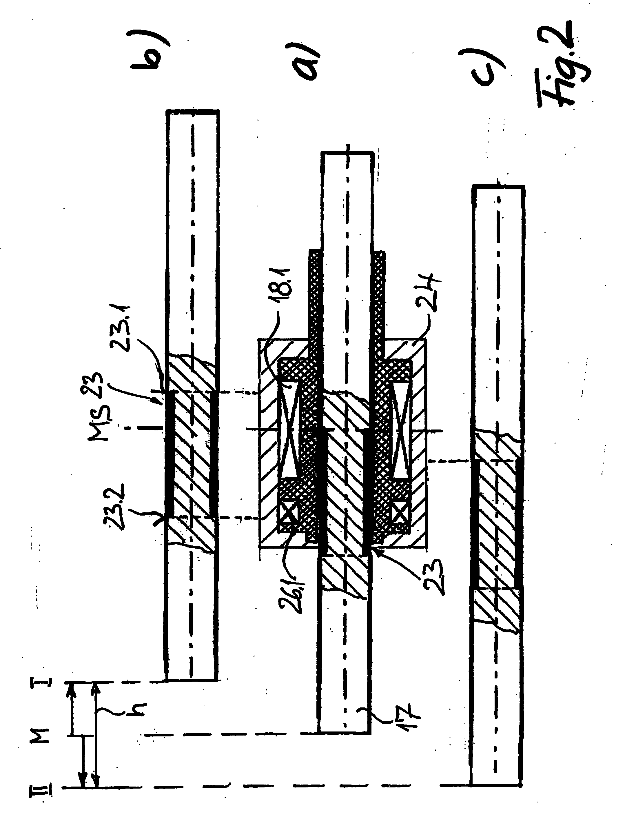
The invention relates to a sensor array for detecting travel of a movable member, especially a positioning element that is movable using an actuator. Said sensor array comprises a stationary coil arrangement (18) that is provided with an active coil (18.1) and at least one passive coil (26.1, 26.2) located a distance therefrom. The coil arrangement (18) is connected to a power supply unit (30) and a signal-detecting device (29). The inventive sensor array further comprises an axially movable rod-shaped sensor part (17) that is made of a preferably magnetizable material, is connected to the positioning element which is movable fore and aft in an axial direction, and is provided with at least one short circuit element (23, 23.0). Said at least one short circuit element (23, 23.0) is made of an electrically conducting material having low ohmic resistance, is delimited by a final edge (23.1, 23.2) in the longitudinal direction, respectively, and has a dimension in the direction of movement, which is calculated such that one final edge (23.1, 23.2, 23.3) of the at least one short circuit element (23) is enclosed by the active coil (18.1) in at least one final position (I, II) defined by the predefined length of stroke (h) while another final edge (23.1, 23.2, 23.3) of the at least one short circuit element (23, 23.0) is at least partly embraced by one of the at least one passive coils (26.1, 26.2).

Description

BACKGROUND OF THE INVENTION [0001] In an actuator for moving a positioning element back and forth, particularly an electromagnetic actuator, the movement of the actuator armature is typically identical to the movement of the positioning element to be actuated, such that it is possible to measure the armature movement and consequently the movement of the positioning element in the region of the actuator. [0002] In an electromagnetic actuator with two spaced-apart electromagnets, the pole faces of which point toward one another and between which an armature is guided such that it can be moved back and forth against the force of return springs when the electromagnets are alternately supplied with a current, a measurement of the current and / or voltage at the respective attracting magnet and during release of the restraining magnet makes it possible to draw conclusions about the armature movement that can subsequently be used for control purposes if the signals are processed appropriatel...

Claims


Application Information

Patent Timeline
Patent Type & Authority Applications(United States)
IPC IPC(8): G01B7/14F02M59/44F02M61/16F02M65/00G01D5/22
CPCF02M59/44G01D5/2225F02M65/005F02M61/16
Inventor GURICH, GUNTERLAUMEN, HERMANN-JOSEFWEBER, RALF
Owner FEV MOTORENTECHN GMBH
Why Eureka
Eureka Blog
Learn More