Motor controller

a brushless direct current motor and motor controller technology, applied in the direction of motor/generator/converter stopper, dynamo-electric converter control, dc motor rotation control, etc., can solve the problems of erroneous operation of transistor switches, and affecting the operation of motors. precise speed adjustment, accurate control of transistor conduction and non-conductivity

Inactive Publication Date: 2007-07-05
YEN SUN TECH CORP
View PDF5 Cites 601 Cited by
  • Summary
  • Abstract
  • Description
  • Claims
  • Application Information

AI Technical Summary

Benefits of technology

[0010] Therefore, the object of the present invention is to provide a motor controller which utilizes a processor to detect a change in voltage drop when the direction of current flow through a drive coil is switc

Problems solved by technology

However, a back electromotive force effect is likely to occur at the instant the direction of current flow through the coil 15 is switched, which can lead to erroneous operation of the transistor switches 11 to 14 and which can result in possible damage to the transistors switches 1

Method used


Image

  • Motor controller
  • Motor controller
  • Motor controller

Examples


Embodiment Construction

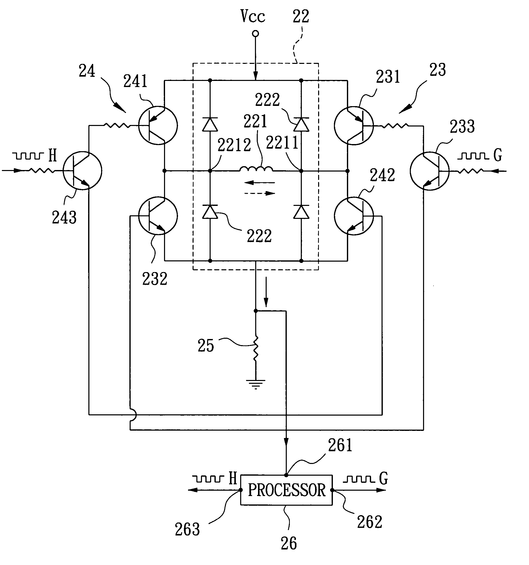
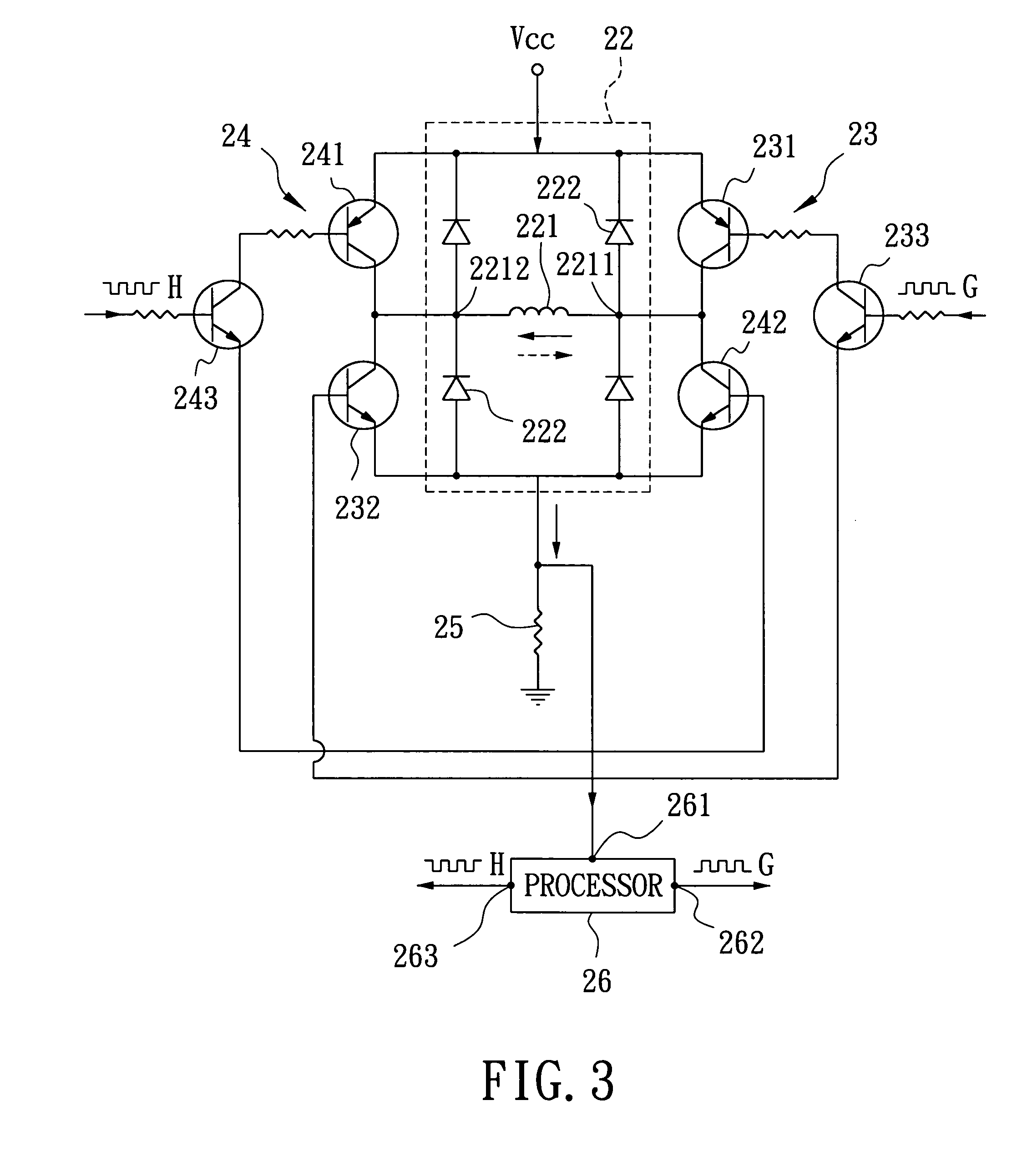
[0016] Referring to FIG. 3, the preferred embodiment of a motor controller 2 according to the present invention is adapted for driving rotation of a magnetic rotor (not shown) of a brushless direct current motor, and is shown to include a power source unit (Vcc) for providing a smooth and stable direct current output, a drive unit 22, first and second transistor units 23, 24, a voltage drop component 25, and a processor 26.

[0017] The drive unit 22 is coupled electrically to the power source unit (Vcc), and includes a drive coil 221 (which is wound on a stator of the motor), a first set of diodes 222 coupled electrically and respectively between opposite ends 2211, 2212 of the drive coil 221 and the power source unit (Vcc), and a second set of diodes 222 coupled electrically and respectively between the opposite ends 2211, 2212 of the drive coil 221 and the voltage drop component 25. The diodes 222 cooperate with the drive coil 221 to form an H-bridge configuration, and serve to pro...


PUM


Abstract

A motor controller includes a power source unit providing a direct current output, a drive unit including a drive coil, first and second transistor units, a voltage drop component, and a processor. The transistor units are coupled to the power source unit and the drive unit, and enable electricity to flow through the drive coil in a first direction when the first and the second transistor units are in conducting and non-conducting states respectively, and in an opposite second direction when the first and the second transistor units are in non-conducting and conducting states respectively. The voltage drop component has a first end coupled to the drive unit and a grounded second end. The processor is coupled to a junction of the drive unit and the voltage drop component, and provides first and second pulse-width-modulated signals to the first and second transistor units, respectively.

Description

CROSS-REFERENCE TO RELATED APPLICATION [0001] This application claims priority of Taiwanese application no. 094147508, filed on Dec. 30, 2005. BACKGROUND OF THE INVENTION [0002] 1. Field of the Invention [0003] The invention relates to a controller for a brushless direct current motor, more particularly to a motor controller that is capable of precise speed adjustment using pulse width modulation (PWM) techniques. [0004] 2. Description of the Related Art [0005] In a conventional brushless direct current motor, when electricity is conducted through a stator coil, a Hall IC is adopted to determine the positions of north and south poles of a magnetic rotor so that the direction of current flow through the stator coil can be varied to generate an alternating magnetic field, thus producing magnetic repulsive forces to cause continuous rotation of the magnetic rotor. Moreover, pulse width modulation (PWM) is a common technique used for speed control of a motor, such as a fan motor. [0006]...

Claims


Application Information

Patent Timeline
IPC IPC(8): H02P1/00H02P3/00H02P6/06H02P6/08H02P6/26
CPCH02P7/0044H02P7/04
Inventor CHEN, CHIEN-JUNGLIANG, I-RONG
Owner YEN SUN TECH CORP
Why Eureka
Try Eureka