
Quartz glass crucible and method for treating surface of quartz glass crucible

a technology of quartz glass and crucible, which is applied in the direction of crystal growth process, crystal growth process, polycrystalline material growth, etc., can solve the problems of pitting corrosion and reducing yield, and achieve the effect of reducing chemistry, prolonging the life of quartz glass crucible, and reducing chemistry

Inactive Publication Date: 2007-07-05
GENERAL ELECTRIC CO
View PDF27 Cites 6 Cited by
  • Summary
  • Abstract
  • Description
  • Claims
  • Application Information

AI Technical Summary

Benefits of technology

[0013] In one aspect, the invention further relates to a method to extend the life of a quartz glass crucible by coating a surface of the quartz glass crucible with a coating material with at least one of: a) effecting a dispersal of crystalline silicon dioxide nuclei in a gel film containing a silane or germane compound; b) effecting a reduced chemistry on the surface of the quartz glass crucible by the application of a silane or germane compound; and c) a sufficient amount of a germanium compound to effect a relief of tensile stresses in the grown silicon crystal, wherein the quartz glass surface upon exposure to melted silicon forming rosettes or crystalline morphology covering at least 75% of the coated surface of the quartz glass crucible.
[0016] In yet another aspect, the invention relates to a process to extend the life of quartz glass articles by varying the reduction / oxidation state of the surface of the crucibles in a surface treating process. The inner surface of the crucible is coated in a manner with a material which provides the quartz surface with a dispersal of crystalline silicon dioxide compounds to act as nuclei for crystal growth. In one embodiment, additional compounds are used to act as a gel or film to hold those physical nuclei in place, for reducing compound structures that are more chemically reduced than SiO2 to form additional nuclei when the quartz glass surface is used in operation.

Problems solved by technology

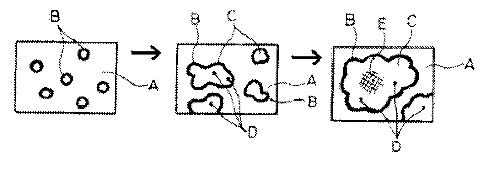
And as the glass surface (E) is eroded or dissolved, it dissolves non-uniformly and is very likely to let loose particles into the melt which are apt to cause dislocations in the silicon crystal growth and thus reducing the yield.
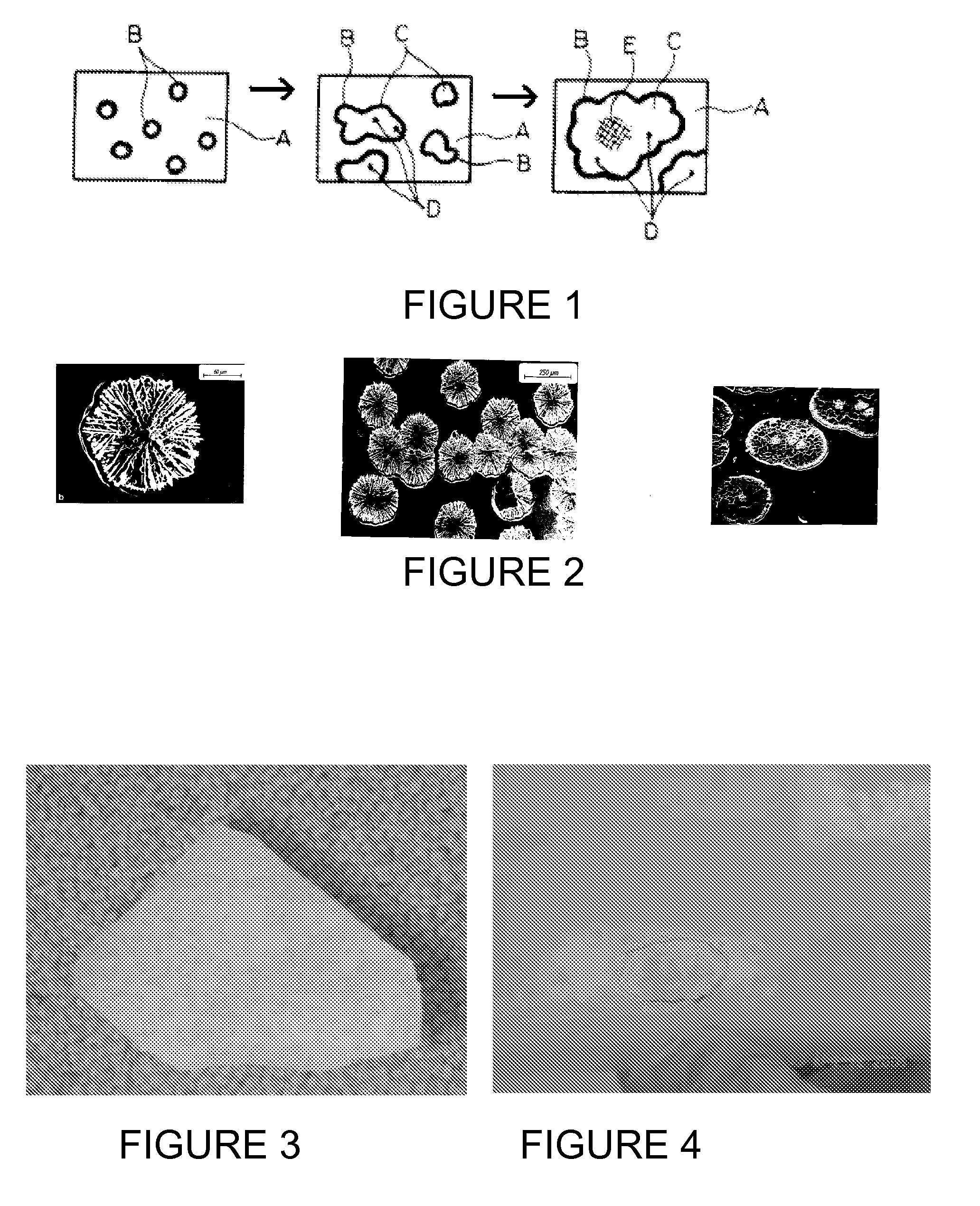
Eventually, portions of the rosettes begin to flake out, and very often it is the center of the rosettes which begin to flake out as illustrated in FIG. 4, thus causing pitting corrosion.
However, even the best attempts to approach thermodynamic / slow growth conditions still incorporate the vacancies.

Method used


Image

  • Quartz glass crucible and method for treating surface of quartz glass crucible
  • Quartz glass crucible and method for treating surface of quartz glass crucible
  • Quartz glass crucible and method for treating surface of quartz glass crucible

Examples


example 1

[0077] A untreated crucible from GE Quartz of Willoughby, Ohio, USA is first washed with silicon tetrachloride, then subsequently coated with a Redox coating of (CH3)2SiCl2 dissolved in 1,1,1 trichloroethane at a ratio of 1:4. The coating is done manually by brushing the entire crucible surface with the solution, with the excess being wiped off.

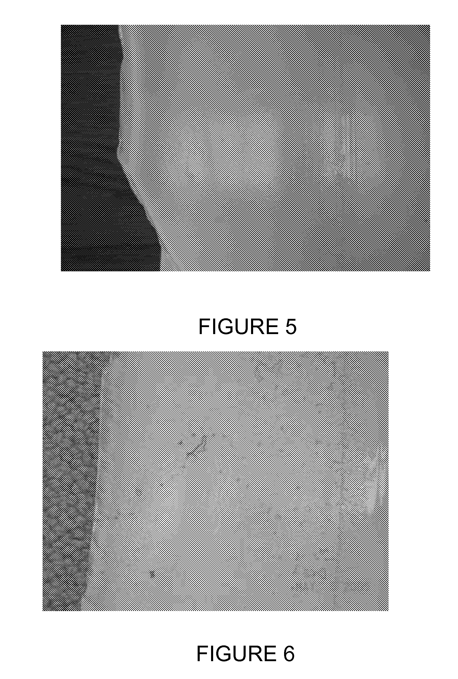
[0078] In operation and after the first Czochralski crystal pulling run, a number of densely formed brown rings are observed on parts of the coated crucible surface as shown in FIG. 5. The crucible surface develops a higher than normal density of rosettes (as represented by the brown rings) of at least 50%, compared to the number of brown rings appearing on an untreated crucible after such a crystal pulling run. Further, the rosettes are stable for the entire length of the run and show no degradation in the center.

[0079] Besides the increased number of “brown rings” or density of rosettes, the rosettes are more well formed and appear to be ...

example 2

[0080] A coupon cut from an untreated crucible from GE Quartz of Willoughby, Ohio, USA is first washed with silicon tetrachloride, then subsequently coated with a Redox coating of (CH3)2SiCl2 dissolved in 1,1,1 trichloroethane at a ratio of 1:4. The coating is done manually by brushing the entire crucible surface with the silane solution. After coating, the excess solvent evaporates leaving the coating in place. The excess byproduct of the coating chemical is removed and the crucible is ready to use.

[0081] The coupon is exposed to melted silicon at a temperature in excess of 1420° C. and for 30 to 60 hours, simulating the condition of a Czochralski crystal pulling run. The coupon is removed from the melted silicon and observed under microphotography. Densely formed brown rings are observed covering at least 80% of the surface of the coupon (previously treated with the Redox coating). Additionally, the rosettes within the brown rings appear to be very thick and very robust, with no ...

example 3

[0082] In this example, an untreated 22 inch crucible from GE Quartz of Newark, Ohio, USA was tested in a silicon crystal pulling operation vs. an embodiment of a crucible of the invention, a 22 inch crucible that was first washed with silicon tetrachloride, then subsequently coated with a Redox coating of (CH3)2SiCl2 dissolved in 1,1,1 trichloroethane at a ratio of 1:4 per procedure in Example 2. The yield after the first pass for the untreated crucible was less than ½ of the yield obtained for the coated crucible of the invention. Yield is measured as inches of good silicon crystal obtained from a run.


PUM

PropertyMeasurementUnit
temperatureaaaaaaaaaa
melting temperaturesaaaaaaaaaa

Abstract

There is provided a quartz glass article having a surface treated with novel coating materials which provides a reduced chemistry, wherein the quartz glass surface having a reduced chemistry upon exposure to melted silicon or similarly corrosive environments, forms crystalline structures covering at least 75% of the coated surface of the quartz glass crucible. Said crystalline covered surface provides a more stable surface of contact with the silicon melt and the growth of single crystal silicon. In one embodiment of the invention, the coating material comprises at least a methyl group for providing at least one of a hydrogenated and a methylated surface on the coated surface, forming rosette structures, or other crystalline morphologies covering at last 80% of the coated surface. In another embodiment of the invention, the coating material is selected from at least one of an amine, an organosilane halogen and mixtures thereof.

Description

CROSS REFERENCE TO RELATED APPLICATIONS [0001] This application claims the benefits of U.S. 60 / 728,216 filed Oct. 19, 2005 which patent application is fully incorporated herein by reference.FIELD OF THE INVENTION [0002] The present invention relates to quartz glass articles, including quartz glass crucibles used for pulling a silicon single crystal in the semiconductor industry, and methods for treating the surface of quartz glass articles. BACKGROUND OF THE INVENTION [0003] Single crystal silicon, which is the starting material for most semiconductor electronic component fabrication, is commonly prepared by the so-called Czochralski (“Cz”) method. Using the Cz method, the growth of the crystal is carried out in a crystal-pulling furnace, wherein polycrystalline silicon (“polysilicon”) is charged to a crucible and melted by a heater surrounding the outer surface of the crucible sidewall. A seed crystal is brought into contact with the molten silicon and a single crystal ingot is gro...

Claims


Application Information

Patent Timeline
Patent Type & Authority Applications(United States)
IPC IPC(8): C30B15/00
CPCC03C17/004C03C17/006C03C17/28C03C17/30Y10T117/1032C03C2217/42C30B15/10C30B29/06C30B35/002C03C2217/40C03C17/00
Inventor HANSEN, RICHARD LEEKIRCHER, THEODORE P.DEVANATHAN, NARSI
Owner GENERAL ELECTRIC CO
Learn More