Fuel cell disassembly method

a technology of disassembly and fuel cell, which is applied in the direction of secondary cell servicing/maintenance, insulating conductor/cable, and primary cell maintenance/service, etc. it can solve the problems of difficulty in effectively disassembling the fuel cell, accidental cut in the middle of the linear member, etc., and achieves convenient and facilitates the separation of the pair of separators

Active Publication Date: 2007-07-05
TOYOTA JIDOSHA KK
View PDF5 Cites 12 Cited by
  • Summary
  • Abstract
  • Description
  • Claims
  • Application Information

AI Technical Summary

Benefits of technology

[0023] In the second fuel cell disassembly method of tile invention, it is further preferable that the separation facilitating step causes the external heat removal means to remove heat from the adhesive layer, while an external force is applied by external force application means to the adhesive layer in a direction of mutually parting the pair of separators. While the adhesive layer is cooled down and contracted to weaken the adhesive force between the pair of separators, the external force is applied in the direction of mutually parting the pair of separators. This arrangement thus further facilitates separation of the pair of separators. The external force application means may be a wedge-like member pressed in a direction of insertion into a gap between the pair of separators. As the adhesive force of the adhesive layer is weakened, the wedge-like member enters the depth of the gap between the pair of separators to expand the gap. This arrangement thus further facilitates separation of the pair of separators. The external force application means may be inserted into the gap between the pair of separators while being cooled down for heat removal by the external heat removal means. This arrangement ensures additional removal of heat from the adhesive layer via the external force application means. The external force application means may apply the external force to an extension of one of the separators to separate one of the separators from the other of the separators. This structure uses the extension of one of the separators to easily separate the pair of separators from each other. The extension maybe rims provided on side faces of the separator.
[0024] In the second fuel cell disassembly method of the invention, it is preferable that the separation facilitating step causes the external heat removal means to remove heat from the adhesive layer while applying an external force to the adhesive layer in a direction of mutually parting the pair of separators. While the adhesive layer is cooled down and contracted to weaken the adhesive force between the pair of separators, the external force is applied in the direction of mutually parting the pair of separators. This arrangement thus further facilitates separation of the pair of separators. This arrangement does not require the external force application means, i...

Problems solved by technology

The linear member may, however, accidentally be cut in the middle or may not be easily move...

Method used


Image

  • Fuel cell disassembly method
  • Fuel cell disassembly method
  • Fuel cell disassembly method

Examples


first embodiment

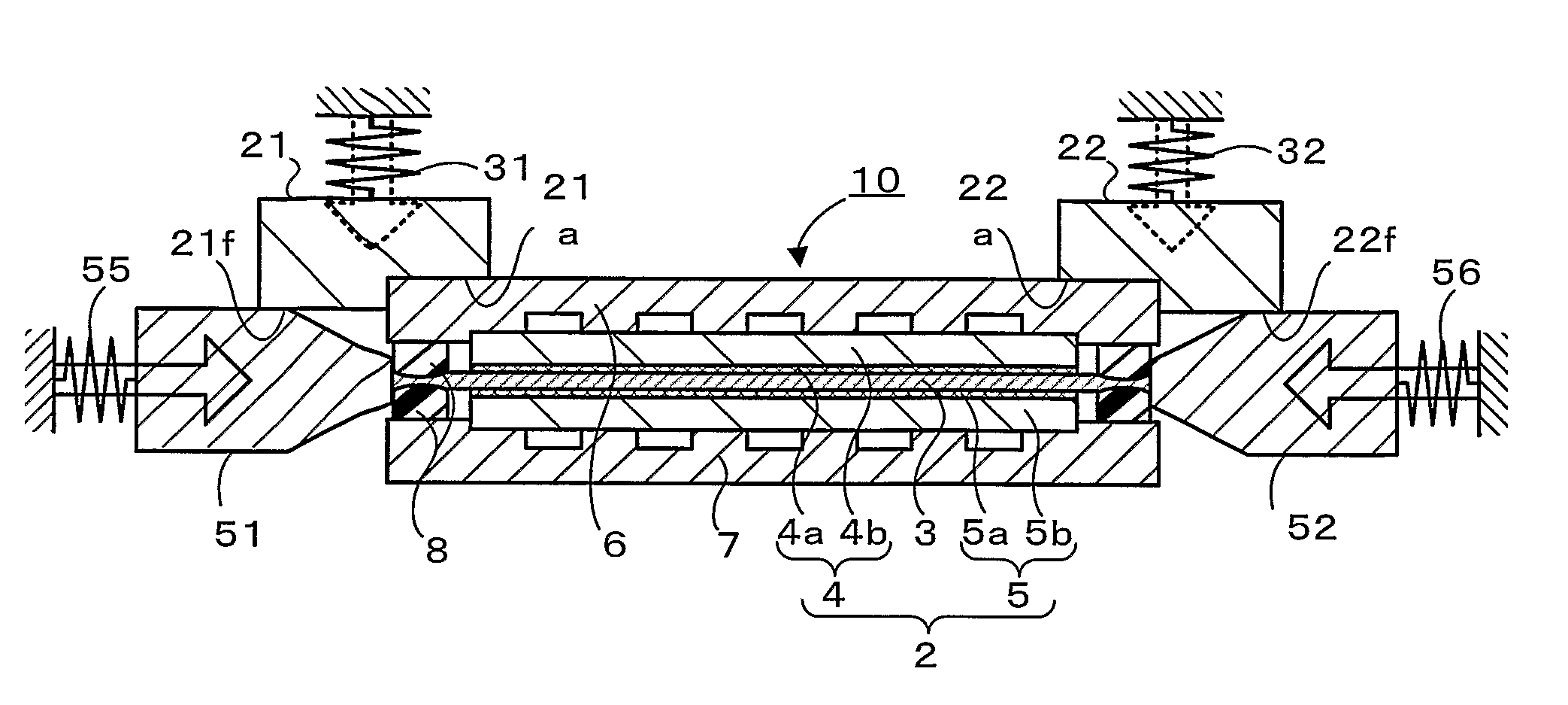
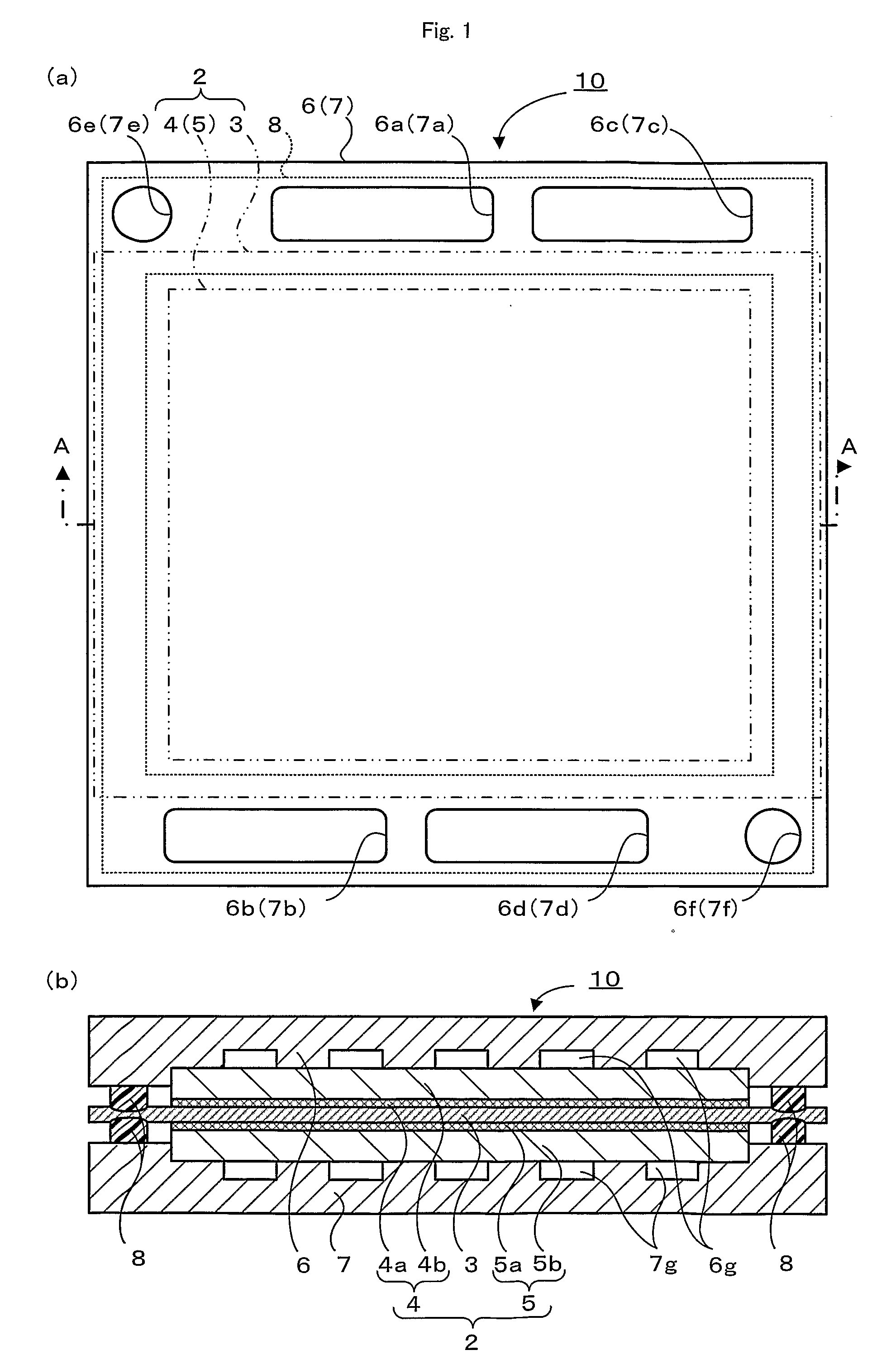
[0031]FIG. 1 schematically illustrates the structure of a fuel cell 10 in a first embodiment of the invention. FIG. 1(a) is a plan view, and FIG. 1(b) is a sectional view taken on a line A-A of FIG. 1(a).

[0032] The fuel cell 10 of this embodiment is a polymer electrolyte fuel cell and includes, as main constituents, a membrane electrode assembly (hereafter referred to as MEA) 2 having an electrolyte membrane 3 interposed between a pair of electrodes 4 and 5, sealing layers 8 located to surround the outer circumference of the MEA 2, and a pair of separators 6 and 7 arranged across the MEA 2 and bonded to the sealing layers 8. The fuel cell 10 is a unit cell having an electromotive force in a range of about 0.6 to 0.8 V. A large number of the fuel cells 10 are tightly laid one upon another to form a direct current power source of several hundred volts as a power supply of, for example, a drive motor of the vehicle.

[0033] The MEA 2 has the electrolyte membrane 3 located between the f...

second embodiment

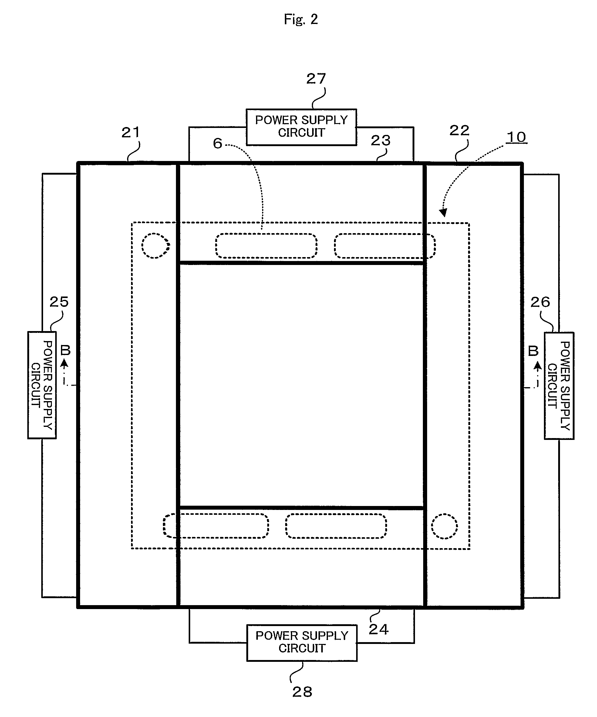
[0046] A second embodiment of the invention regards a fuel cell stack 70, which is a layered body of plurality of the fuel cells 10. FIG. 12 is a perspective view showing the fuel cell stack 70 in the state of power generation in the second embodiment of the invention. FIG. 13 is a sectional view taken on a line B-B of FIG. 12. In the illustration of FIGS. 12 and 13, the respective constituents of the fuel cells 10 are expressed by the like numerals and symbols to those of the first embodiment.

[0047] As shown in FIG. 12, the fuel cell stack 70 has a cell laminate of the multiple fuel cells 10 of the first embodiment, which are closely and tightly layered one upon another, and end plates 73 and 74 that are arranged across the cell laminate via insulator plates 71 and 72 and are pressed in a compression direction with a pressing force F1 applied by a pressure device (not shown). The fuel cell stack 70 is used as a power source of several hundred volts. The end plate 73 shown on the f...

third embodiment

[0055] A third embodiment of the invention regards a method of disassembling the fuel cell 10 according to the requirements. FIG. 15 shows arrangement of heat removers 121 through 124 set on the fuel cell 10. FIG. 15(a) is a plan view and FIG. 15(b) is a sectional view taken on the line F-F of FIG. 15(a). The like elements to those of the first embodiment are expressed by the like numerals and are not specifically described here. The metal heat removers 121 through 124 of good heat conduction are cooled down to minus several tens ° C. in a freezer and are taken out of the freezer at the time of disassembly of the fuel cell 10. As shown in FIG. 15, the cooled heat removers 121 through 124 are located along four sides of the upper separator 6 of the fuel cell 10, that is, along the sealing layers 8. These heat removers 121 through 124 correspond to the external heat removal means of the present invention. As shown in FIG. 15(b), the heat removers 121 and 122 are formed in substantiall...


PUM

PropertyMeasurementUnit
Temperatureaaaaaaaaaa
Forceaaaaaaaaaa
Heataaaaaaaaaa

Abstract

Respective heaters 21 through 24 receive power supply and start heating. The heaters 21 through 24 keep heating sealing layers 8 to or over a softening temperature at which the sealing layers 8 are softened or molten. After the sealing layers 8 are softened or molten to weaken the adhesive force between a pair of separators 6 and 7, the heaters 21 through 24 are detached from a fuel cell 10. The worker then completely separates the pair of separators 6 and 7 from each other with some tool or by hand and removes an MEA 2 from the fuel cell 10.

Description

FIELD OF INVENTION [0001] The present invention relates to a fuel cell disassembly method of disassembly a fuel cell or a fuel cell stack. BACKGROUND ART [0002] A fuel cell of a known structure includes: an electrode assembly that has an electrolyte interposed between a pair of electrodes; sealing layers that are formed along periphery of the electrode assembly; and a pair of separators that are arranged across the electrode assembly and bonded to each other via the sealing layers, where one of the separators facing one of the electrodes has an oxidizing gas conduit, while the other of the separators facing the other of the electrodes has a fuel gas conduit. In the fuel cell of this known structure, a supply of hydrogen is fed as a fuel gas to the fuel gas conduit, whereas a supply of the air is fed as an oxidizing gas to the oxidizing gas conduit. Hydrogen is separated into proton and electron at one of the electrodes (anode) facing the fuel gas conduit. The proton passes through t...

Claims


Application Information

Patent Timeline
IPC IPC(8): B23P19/00H01M8/00H01M8/02H01M8/04H01M8/10H01M8/24
CPCH01M8/008H01M8/0276H01M8/04067H01M8/10H01M8/241Y10T156/1153H01M8/247H01M8/2485Y02E60/50Y10T29/49815Y10T156/1911H01M8/2465Y02W30/84
Inventor SUZUKI, HIROSHIYODOSHI, NOBUOTEJIMA, GONAKASHIMA, TOMOAKIAKAGAWA, RYO
Owner TOYOTA JIDOSHA KK
Why Eureka
Try Eureka