
Cryoprobe for low pressure systems

Inactive Publication Date: 2007-06-28
SANARUS TECHNOLOGIES
View PDF20 Cites 41 Cited by
  • Summary
  • Abstract
  • Description
  • Claims
  • Application Information

AI Technical Summary

Benefits of technology

[0005] The devices and methods described below provide for the cryo-ablation of a mass of targeted tissue. The devices include a probe with structures that permit the surgeon to secure and form an ice mass of a suspect mass or tumor. The probe is provided with a rigid tube and a sharp distal segment. To secure the tumor to the probe, the surgeon pierces the tumor with the distal segment. Inlet tubing extending within the rigid tube directs coolant to the distal tip to cool the tip. A helical-shaped baffle comprising a heating element is provided in the distal section of the cryoprobe to create turbulent fluid and improve heat transfer. Since the baffle comprises a heating element, it can be further used in rapid freezing and warming cycles directed at targeted tissue masses.

Problems solved by technology

Present cryoprobes utilizing Joule-Thomson systems have inherent disadvantages such as inefficient heat transfer, the possible occurrence of vapor lock and excessive use of cryogen.
As a result, these systems require use of large quantities of gasses under high pressure and high flow rates, in part, to prevent vapor lock.
Use of high-pressure gasses increases the overall costs of cryoprobes.
This is due to the higher costs of materials required for use with systems utilizing high-pressure gases, the high cost associated with keeping source gases themselves at higher pressures and the large quantities of cryogen required for use with these systems.

Method used


Image

  • Cryoprobe for low pressure systems
  • Cryoprobe for low pressure systems
  • Cryoprobe for low pressure systems

Examples


Embodiment Construction

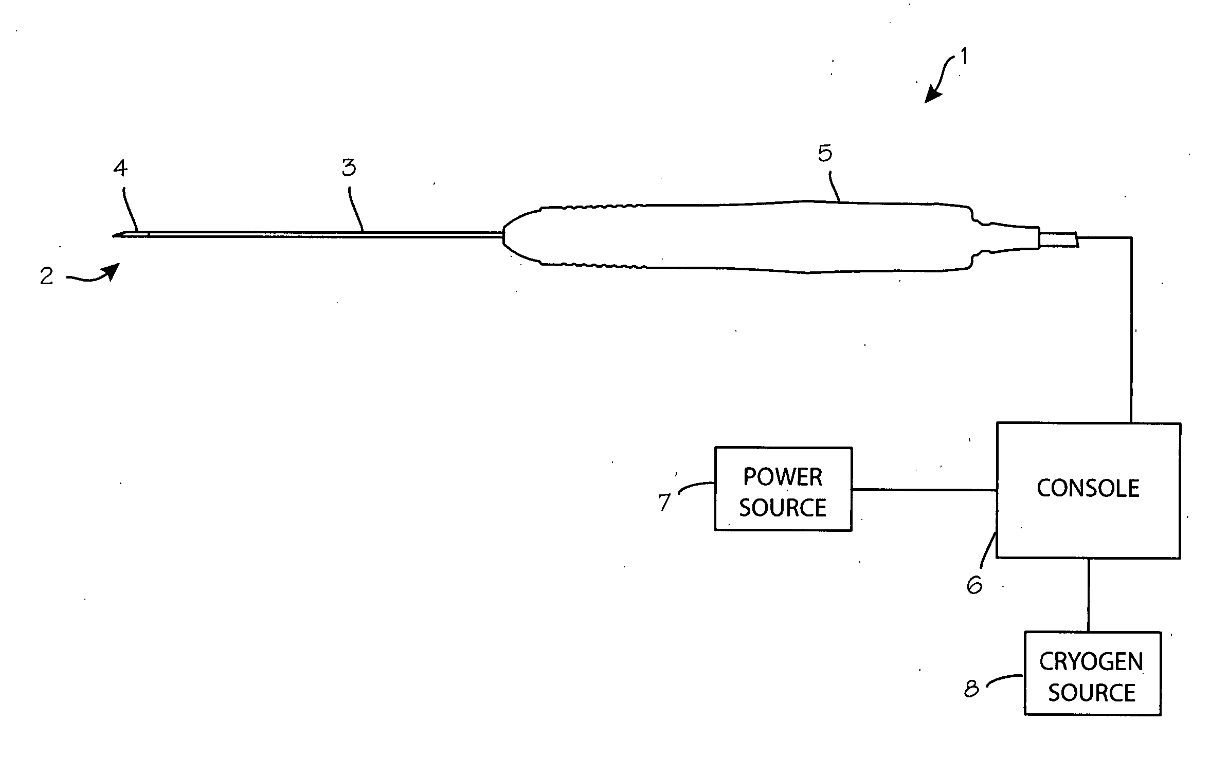
[0013]FIG. 1 illustrates a cryoprobe 1. The cryoprobe uses liquid nitrogen cooling to create a cooled region at the distal end 2. This cooled region adheres to a targeted lesion or tumor and creates an ice mass from the targeted tissue. The cryoprobe comprises a long, slender yet rigid outer tube 3. A short rigid penetrating segment 4 extends distally from the distal end of the rigid tube, and a suitable handle 5 is mounted on the proximal end of the tube. The handle is placed in fluid communication with a console 6 and the console is place in electrical communication with a power source 7 and fluid communication with a cryogen source 8. The console has a control system that is able to regulate use of power and the flow of cryogen to the cryoprobe.

[0014]FIG. 2 shows a partial sectional side view of the distal end portion of the cryoprobe 1 while FIG. 3 shows a partial isometric sectional view of the distal end portion of the cryoprobe 1. The cryoprobe 1 comprises a rigid outer tube...


PUM


Abstract

A cryoprobe for use in cryosurgery and other applications comprising a rigid outer tube, an inner coolant inlet tube a short rigid penetrating segment extending distally from the distal end of the outer tube and a helical-shaped baffle having a heating element disposed about the outer surface of the inlet tube. The baffle is adapted to produce turbulent fluid flow improving heat transfer and is able to warm target tissue during rapid freezing and thawing cycles.

Description

FIELD OF THE INVENTIONS [0001] The inventions described below relate the field of cryoprobes and more specifically to cryoprobes used in surgical procedures. BACKGROUND OF THE INVENTIONS [0002] Cryosurgical probes are used to treat a variety of diseases. The cryosurgical probes quickly freeze diseased body tissue masses, causing the tissue to die after which it will be absorbed by the body, expelled by the body or sloughed off. Cryothermal treatment is currently used to treat prostate cancer and benign prostate disease, breast tumors and breast cancer, liver tumors and cancer, glaucoma and other eye diseases. Cryosurgery is also proposed for the treatment of a number of other diseases. [0003] A variety of cryosurgical instruments, referred to as cryoprobes, cryosurgical ablation devices, and cryostats and cryocoolers, have been available for cryosurgery. The preferred device uses Joule-Thomson cooling in devices known as Joule-Thomson cryostats. These devices take advantage of the f...

Claims


Application Information

Patent Timeline
IPC IPC(8): A61B18/02
CPCA61B18/02A61B2018/0268A61B2018/00041A61B2018/00577A61B2018/0281
Inventor DELONZOR, RUSSELLROSS, JAMESNALIPINSKI, MATHEWTURNER, KEITHFOSTER, DAVIDOAKLEY, TOMCANE, MICHAEL
Owner SANARUS TECHNOLOGIES
Learn More