
Vortex-flow blower device

a blower device and flow technology, applied in the direction of machines/engines, combination engines, liquid fuel engines, etc., to achieve the effect of effectively preventing an impeller

Active Publication Date: 2007-06-28
DENSO CORP
View PDF10 Cites 5 Cited by
  • Summary
  • Abstract
  • Description
  • Claims
  • Application Information

AI Technical Summary

Benefits of technology

[0010]The invention has been made with the above-problems taken into account, and an object of the invention is to provide a vortex-flow blower device, which can effectively prevent an impeller.
[0012]In the vortex-flow blower device, the thermal fuse is fused by a temperature rise so as to discharge the fluid on the side of the discharge port to an outside when the thermal fuse is fused. Alternatively, the thermal fuse is fused by a temperature rise such that the side of the discharge port communicates with the side of the inlet port in the vortex flow chamber when the thermal fuse is fused. Alternatively, the thermal fuse is fused by a temperature rise to be opened. Accordingly, when a state in which discharge load is high is maintained for a long time and the internal temperature of the blower housing rises, the thermal fuse of resin provided in the blower housing is fused and the fluid on the discharge port side can be discharged, thereby the discharge load can be reduced.
[0013]Thus, a temperature rise in the blower housing can be effectively controlled, and it is possible to prevent thermal expansion of the impeller and avoid locking of the impeller. Since locking of the impeller is avoided as mentioned above, the impeller can be prevented from being bursted.
[0014]Even when the blower housing is made of resin, its breakage is avoided because bursting of the impeller does not occur. Since breakage of the blower housing is avoided, the broken pieces of the blower housing do not fly in all directions.

Problems solved by technology

However, when the driving relay of the electric air pump is locked in on state, a harness for bypassing the driving relay is short-circuited, or any other like events for some unexpected reason are assumed as failure in the secondary air supply system, a problem arises.

Method used


Image

  • Vortex-flow blower device
  • Vortex-flow blower device
  • Vortex-flow blower device

Examples


first embodiment

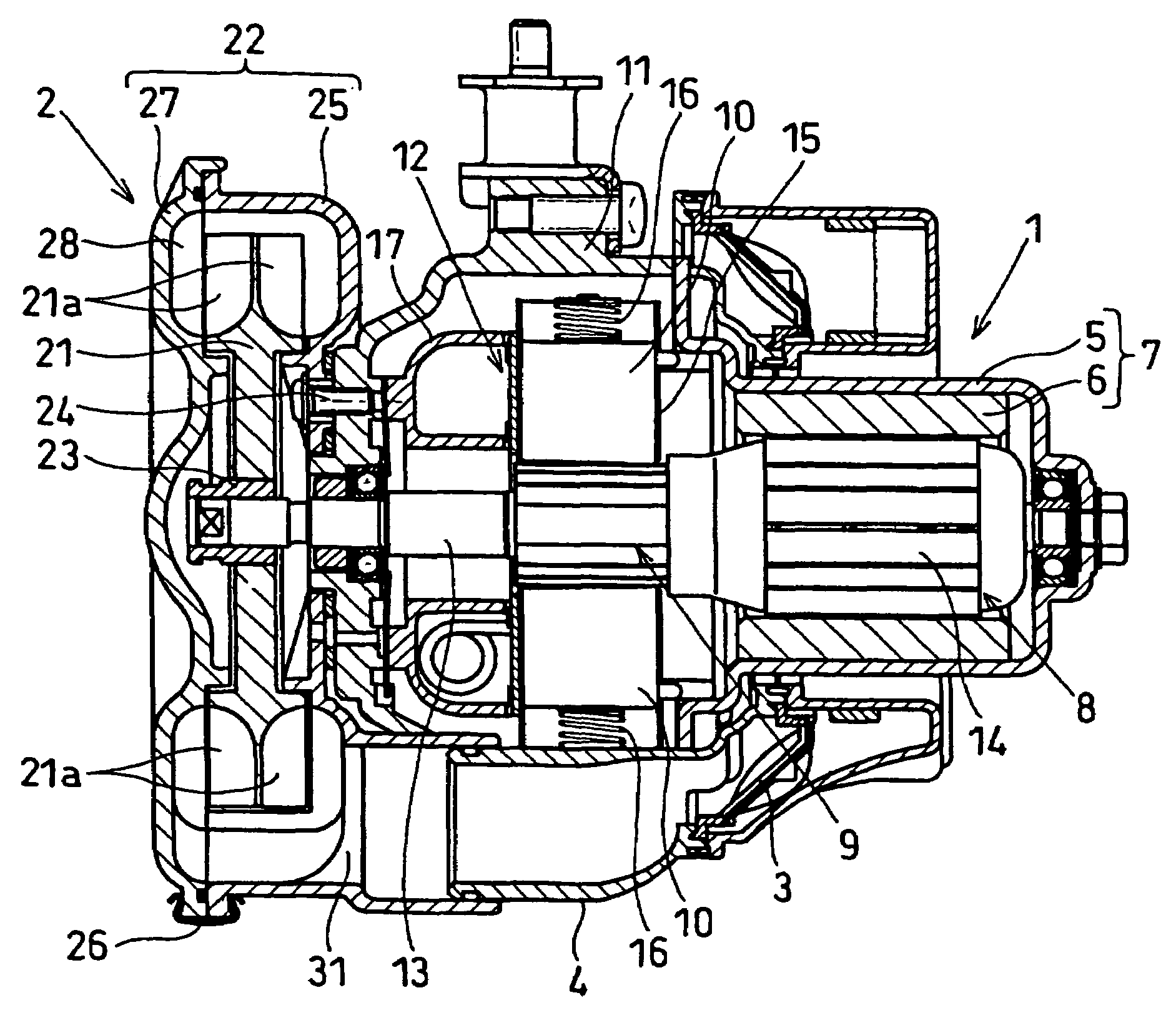
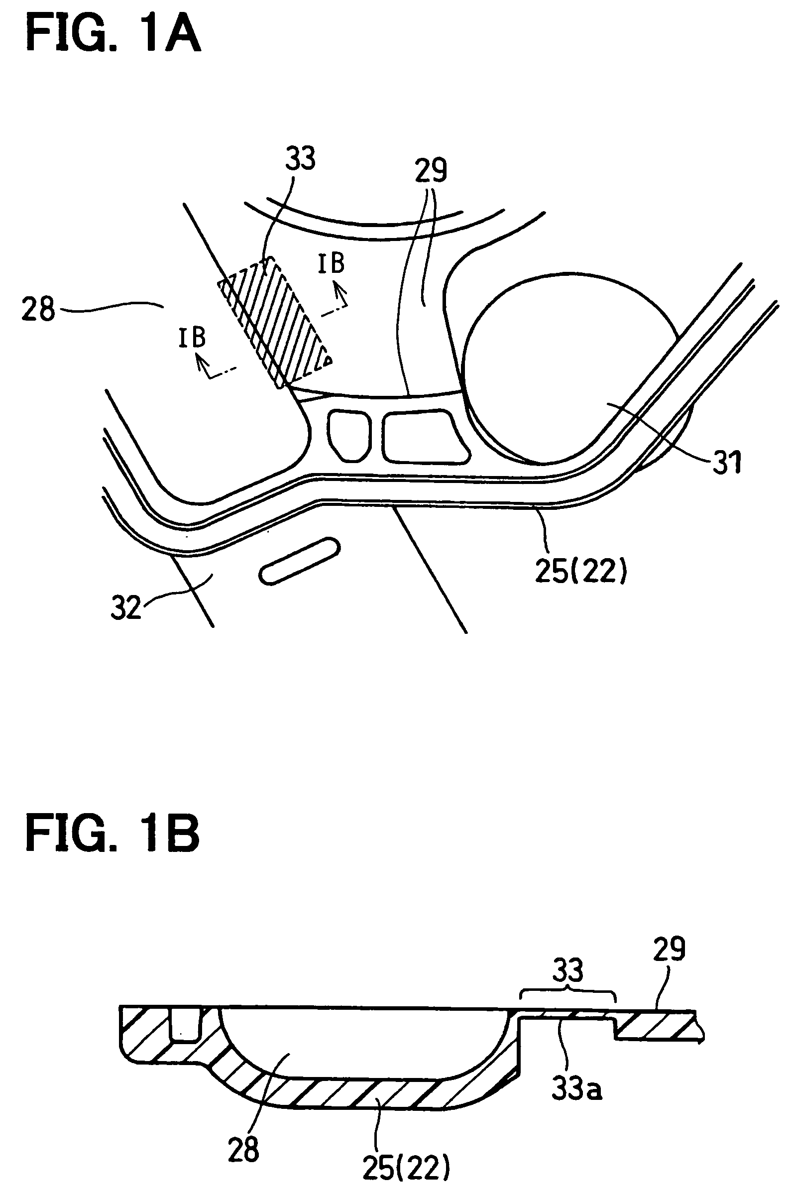
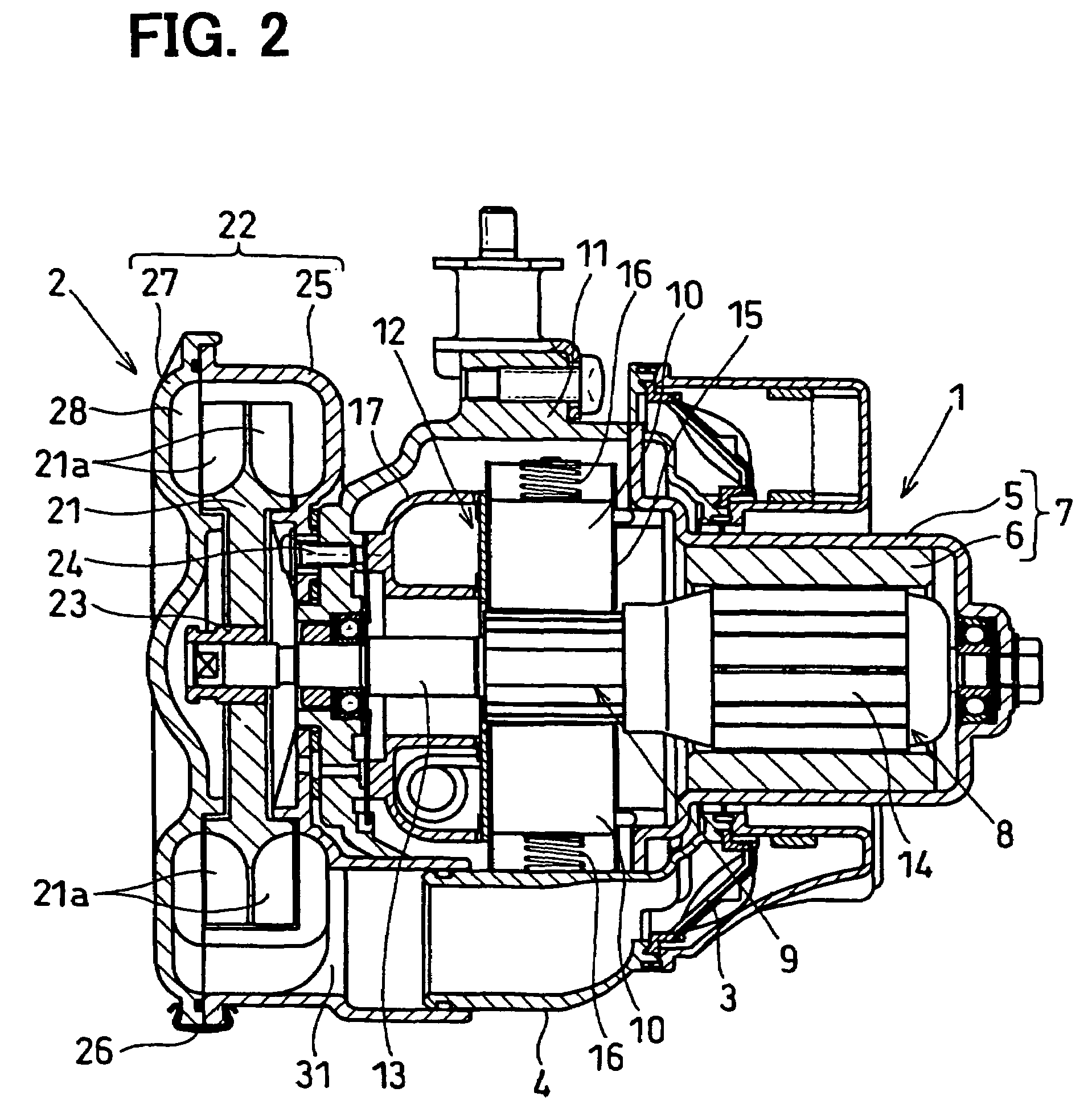
[0023]Description will be given to a first embodiment, in which the invention is typically applied to an electric air pump of a secondary air supply system, with reference to FIGS. 1A and 1B and FIG. 2.

[0024]First, description will be given to an electric air pump with reference to FIG. 2.

[0025]The electric air pump is constructed so as to compress and discharge air when energized. The electric air pump is a supercharger that supplies pressurized secondary air to an area positioned upstream of a catalyst for purifying exhaust gas, mounted in an automobile.

[0026]As illustrated in FIG. 2, the electric air pump in the first embodiment is constructed of an electric motor 1, a vortex flow blower 2, and an air duct 4 with a filter 3 incorporated in it.

[0027]The electric motor 1 shown in the drawing of the first embodiment is a direct-current motor (DC motor). The electric motor 1 is constructed of: a field (stator) 7 constructed by placing multiple magnets 6 on the inner circumferential s...

second embodiment

[0052]Description will be given to a second embodiment with reference to FIGS. 3A and 3B. In the following description of the second embodiment, the same reference numerals as in the description of the first embodiment denote the same functional elements as in the first embodiment.

[0053]In the above example described with respect to the first embodiment, the thermal fuse 33 is provided in the side face (side part) of the partitioning portion 29, close to the discharge port 32.

[0054]In the second embodiment, the thermal fuse 33 is provided in the partitioning portion 29 between the discharge port 32 and the inlet port 31. It is fused by temperature rise, and thereby allows the discharge port 32 side of the vortex flow chamber 28 and the inlet port 31 side of the vortex flow chamber 28 to communicate with each other.

[0055]In the second embodiment, specifically, the thermal fuse 33 is provided in the outer portion of the partitioning portion 29 in the radial direction.

[0056]FIG. 3A ill...

third embodiment

[0060]Description will be given to a third embodiment with reference to FIG. 4.

[0061]With the constructions of the electric air pumps in the first and second embodiments, the following problem may arise when the outdoor air temperature is low in a winter season even when the internal temperature of the blower housing 22 rises. That is, the thermal fuse 33 may be not softened because of outdoor air temperature even when the internal temperature of the blower housing 22 rises.

[0062]To cope with this, the impeller 21 in the third embodiment is so provided that when the temperature in the blower housing 22 rises, the impeller 21 is deformed and is positively brought into contact with the blower housing 22. The blower housing 22 is provided at or in proximity to its portion in contact with the impeller 21 with the thin resin thermal fuse 33. When the temperature rises, this thermal fuse 33 is fused to let out fluid on the discharge port 32 side or allows the discharge port 32 side and th...


PUM


Abstract

A vortex-flow blower device includes an impeller having a plurality of fins, a blower housing that has a vortex flow chamber for accommodating the impeller and extends from a start point on a side of a the fluid inlet port to an end point on a side of a fluid discharge port along the plurality of fins, a partitioning portion that blocks a communication between the end point and the start point in the vortex flow chamber, and a thermal fuse that is provided in the blower housing. The thermal fuse can be fused by a temperature rise so as to discharge the fluid on the side of the fluid discharge port to an outside, or communicate with the side of the fluid discharge port to the side of the fluid inlet port in the vortex flow chamber when the thermal fuse is fused.

Description

CROSS REFERENCE TO RELATED APPLICATION[0001]This application is based on Japanese Patent Application No. 2005-373100 filed on Dec. 26, 2005, the contents of which are incorporated herein by reference in its entirety.FIELD OF THE INVENTION[0002]The present invention relates to a vortex-flow blower device. For example, the vortex-flow blower device can be suitably used for an electric air pump of a secondary air supply system that supplies air to a three-way catalyst converter of a vehicle with pressure.BACKGROUND OF THE INVENTION[0003]As an example of a vortex-flow blower device, there are known electric air pumps used in secondary air supply systems or the like. (Refer to JP-A-2005-69127 corresponding to U.S. 2005 / 0047903 A1, for example.)[0004]In the secondary air supply systems, when an engine has been just started and the temperature of its three way catalyst converter is low, air (secondary air), produced by operating an electric air pump, is guided to the three-way catalyst con...

Claims


Application Information

Patent Timeline
Patent Type & Authority Applications(United States)
IPC IPC(8): F04D5/00
CPCF04D23/008F04D27/008F04D29/4226F04D29/161
Inventor YOKOYAMA, SHINICHITSUZUKI, KUNIHIROSAKATA, MASAKI
Owner DENSO CORP
Learn More