Pupil reflection eye tracking system and associated methods

Inactive Publication Date: 2007-06-28
ALCON REFRACTIVEHORIZONS
View PDF4 Cites 11 Cited by
  • Summary
  • Abstract
  • Description
  • Claims
  • Application Information

AI Technical Summary

Benefits of technology

[0006] The present invention is useful for tracking eye movement by using the eye's retroreflecting properties and a detector, and can be used on dilated and undilated eyes. For small-spot refractive surgery systems, stabilizing the eye is critical for best outcomes. This is typically performed with the use of an eye tracker. A successful tracker has two phases of operation: acquisition and tracking. While tracking is characterized by keeping a particular object in a specific spot relative to a known reference, acquisition is characterized by finding the object within a search volume. If acquisition is not successful, either the tracker will not engage, or will track the wrong object.

Problems solved by technology

If acquisition is not successful, either the tracker will not engage, or will track the wrong object.

Method used


Image

  • Pupil reflection eye tracking system and associated methods
  • Pupil reflection eye tracking system and associated methods
  • Pupil reflection eye tracking system and associated methods

Examples


embodiment 40

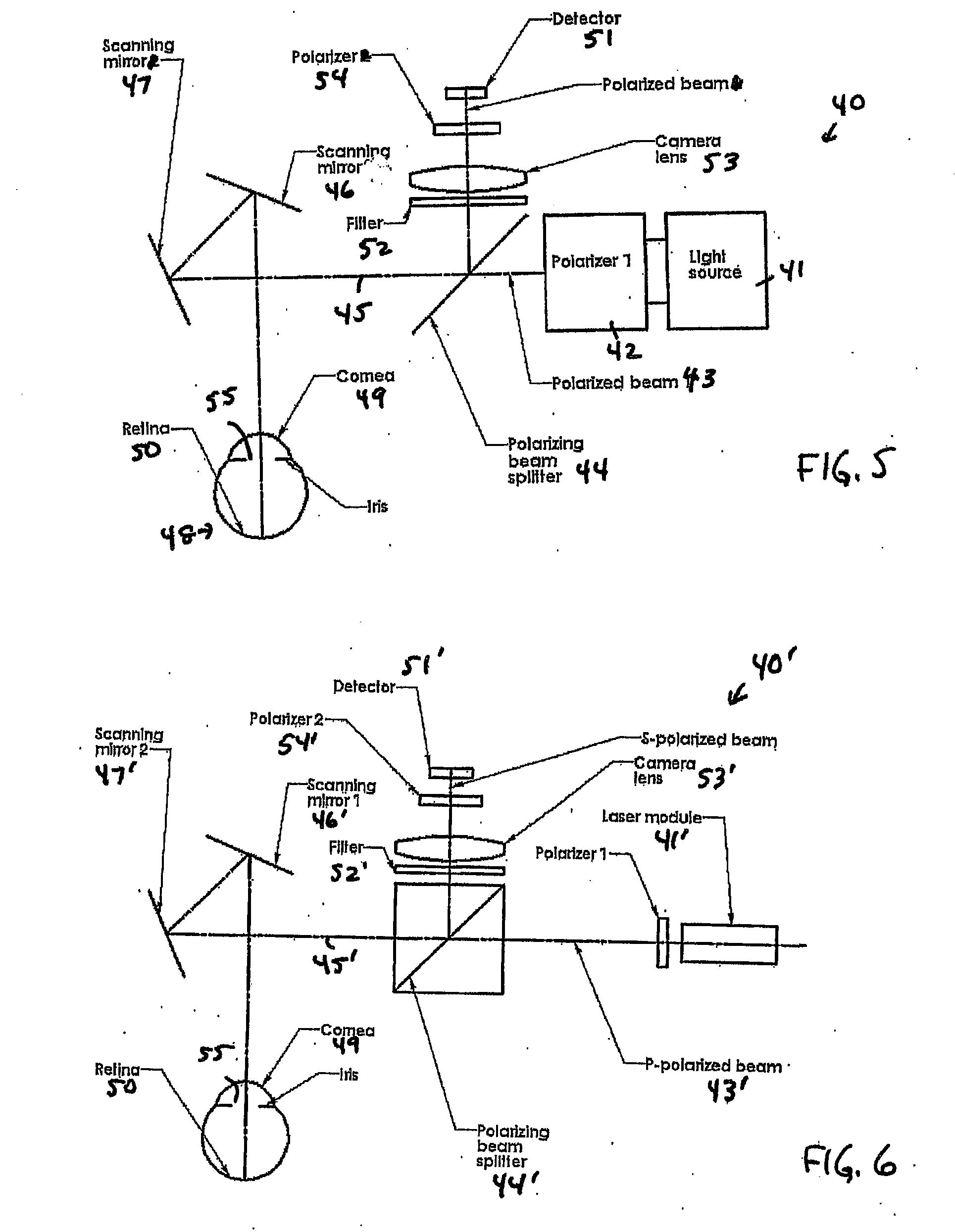
[0043] In an embodiment 40′ (FIG. 6) of the configuration 40 of FIG. 5, the beam 43′ comprises a p-polarized beam. The laser module 41′ can comprise, for example, a laser diode and a collimation / focusing lens. The PBS 44′ passes the p-polarized light and reflects s-polarized light. The p-polarized light 45′ exiting from the PBS 44′ is reflected by the scanning mirrors 46′,47′. A portion of the light incident on the cornea 49 is reflected by the cornea 49 and remains p-polarized. This cornea-reflected light is further reflected by the scanning mirrors 46′,47′ and passes through the PBS 44′. Another portion of the light incident on the cornea 49 goes through the cornea 49 and is scattered by the retina 50. The pupil 55 is illuminated by retina-scattered light that is unpolarized. Light from the pupil area 55 is reflected by scanning mirrors 46′,47′ and is incident on the PBS 44′. s-polarized light is reflected by the PBS 44′ and passes through the filter 52′, camera lens 53′, and seco...

embodiment 60

[0048] In an embodiment 60′ (FIG. 9) of the configuration 60 of FIG. 8, the laser module 61′ can comprise, for example, a laser diode with a collimating lens 66 in front thereof. The collimated beam is expanded by a beam expander formed by a negative lens 67 and a positive lens 68. The expanded beam then passes through a relay system comprising a first 69 and a second 70 relay lens. A small aperture 71 is placed near the focal position of the first relay lens 69. Following this aperture 71, the incoming Gaussian-shaped beam is transformed into a flat-topped beam, which is then collimated by the second relay lens 70 and focused by a focusing lens 72 onto the cornea / pupil position 49. Thus the pupil 55 is illuminated by a flat-topped beam with a steep edge rather than a Gaussian beam, thereby substantially eliminating return from the iris.

[0049] In another embodiment 60″ (FIG. 10) of the configuration 60 of FIG. 8, high-numerical-aperture (NA) focusing optics 73 is employed to replace...


PUM


Abstract

A system for tracking eye movement includes a detector that is adapted to receive radiation reflected from a retina defining a spatial extent of a pupil of an eye. The detector acts to generate data indicative of a positioning of the received radiation on the detector. A processor is in communication with the detector and has software resident thereon for determining from an analysis of the data a pupil position. A controller is in communication with the processor and with a device for adjusting a direction of radiation emitted by an illumination source responsive to the determined pupil position in order to substantially center the emitted radiation on the pupil. The illumination source is preferably coaxial with the detector, and emits a beam having a diameter less than the pupil diameter.

Description

CROSS-REFERENCE TO RELATED APPLICATION [0001] This application claims priority under 35 U.S.C. § 119 to U.S. Provisional Patent Application No. 60 / 753,157 filed Dec. 22, 2005, the entire contents of which are incorporated herein by reference.FIELD OF THE INVENTION [0002] The invention relates generally to optical tracking systems, and more particularly to optical systems for tracking pupil position. BACKGROUND OF THE INVENTION [0003] In an ophthalmic surgical procedure, unwanted eye movement can degrade the outcome of the surgery. Eye positioning is critical in such procedures as corneal ablation, since a treatment laser is typically centered on the patient's theoretical visual axis which, practically speaking, is approximately the center of the patient's pupil. However, this visual axis is difficult to determine due in part to residual and involuntary eye movement. Therefore, it is critical to stabilize the eye with respect to the surgical apparatus for best outcomes. [0004] Previo...

Claims


Application Information

Patent Timeline
Patent Type & Authority Applications(United States)
IPC IPC(8): A61B3/10
CPCA61B3/113A61B3/12A61B3/156
Inventor LEBLANC, RICHARDSENSIPER, MARTINMCGILVARY, THOMAS
Owner ALCON REFRACTIVEHORIZONS
Why Eureka
Try Eureka