
On-board image-recognizing apparatus, on-board image-shooting apparatus, on-board image-shooting controller, warning apparatus, image recognizing method, image shooting method, and image-shooting controlling method

a technology of image recognition and object recognition, applied in scene recognition, instruments, computing, etc., can solve the problems of delay in detecting objects, data volume increase, and long interval in object recognition

Inactive Publication Date: 2007-06-21
FUJITSU GENERAL LTD
View PDF6 Cites 56 Cited by
  • Summary
  • Abstract
  • Description
  • Claims
  • Application Information

AI Technical Summary

Benefits of technology

The present invention provides an image recognizing apparatus and method for vehicles that can detect potential objects of collision with the vehicle and control the frame rate of image shooting based on the required response rate to detect such objects. This results in improved image quality and faster processing. Additionally, the invention includes a warning apparatus that can provide a warning to the driver or passengers of the vehicle based on the recognition result obtained by the image recognizing unit. Overall, the invention improves safety and efficiency for vehicles equipped with image recognizing technology.

Problems solved by technology

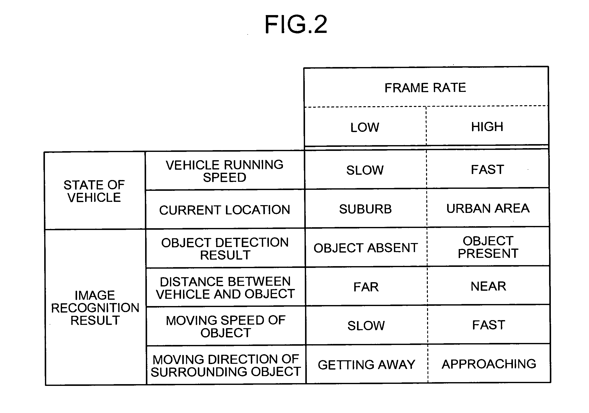
If the frame rate is high, there is an advantage that the movements can be shot or displayed more smoothly; however there is a disadvantage that the data volume increases.
In image recognition, a low frame rate results in a long interval in object recognition.
This may cause a delay in detecting the object or performing warning to the driver of the vehicle.
On the other hand, a high frame rate results in a high processing load, whereby heat release and electric power consumption are increased.

Method used


Image

  • On-board image-recognizing apparatus, on-board image-shooting apparatus, on-board image-shooting controller, warning apparatus, image recognizing method, image shooting method, and image-shooting controlling method
  • On-board image-recognizing apparatus, on-board image-shooting apparatus, on-board image-shooting controller, warning apparatus, image recognizing method, image shooting method, and image-shooting controlling method
  • On-board image-recognizing apparatus, on-board image-shooting apparatus, on-board image-shooting controller, warning apparatus, image recognizing method, image shooting method, and image-shooting controlling method

Examples


Embodiment Construction

[0022]Exemplary embodiments of the present invention will be explained below in detail with reference to accompanying drawings.

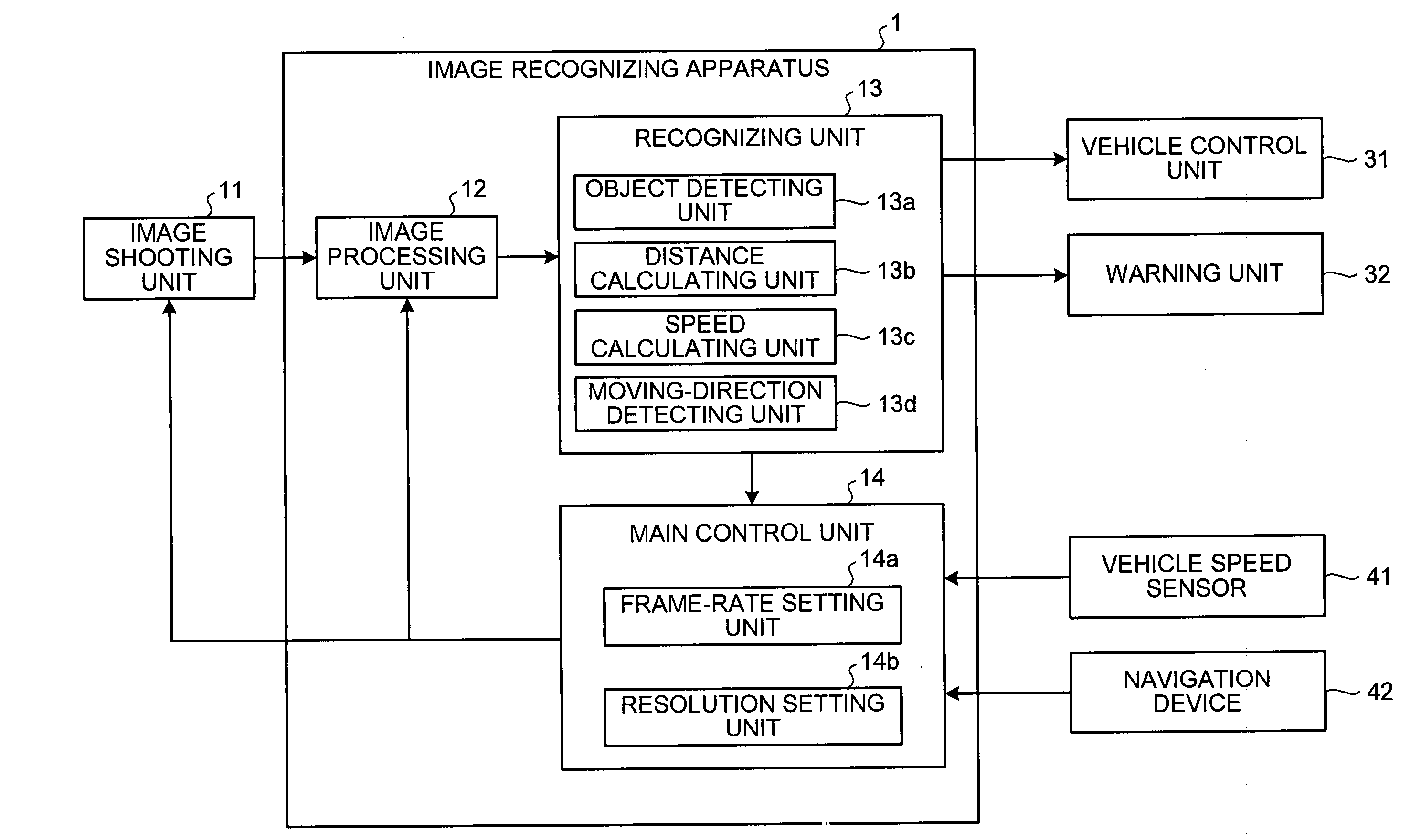
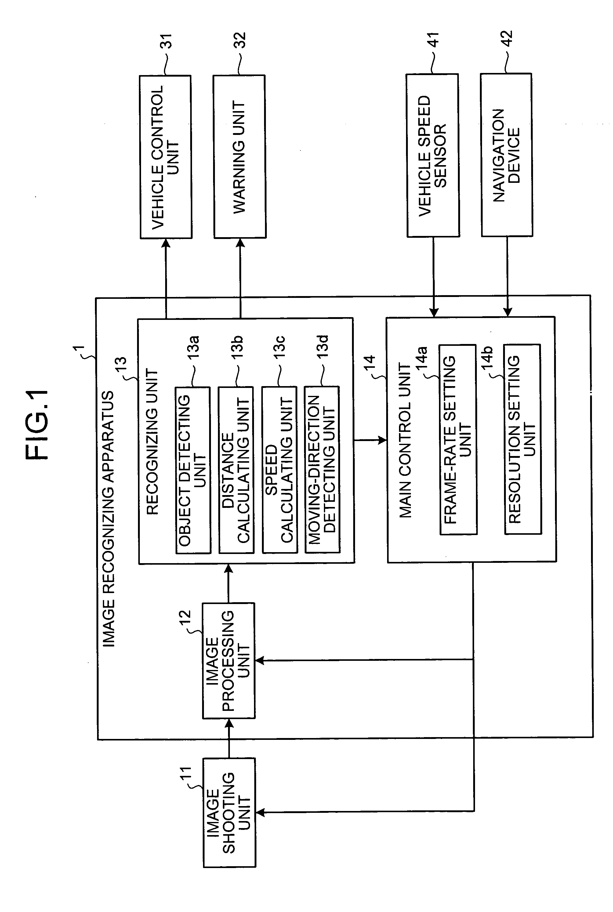
[0023]FIG. 1 is a detailed functional block diagram of an image recognizing apparatus 1 according to an embodiment of the present invention. The image recognizing apparatus 1 is installed on a vehicle. The image recognizing apparatus 1 performs image recognition on an image shot by an image shooting unit 11, which is installed on the vehicle, and performs a feedback control on the image shooting unit 11 so that the image shooting unit 11, shoots an image at a frame rate appropriate to a situation around the vehicle.

[0024]Specifically, the image recognizing apparatus 1 includes an image processing unit 12, a recognizing unit 13, and a main control unit 14. The image shooting unit 11 can be, for example, a charge coupled device (CCD) camera that can acquire frames of a moving picture at a certain frame rate. The frames are passed to the image processing unit 1...


PUM


Abstract

An image shooting unit is installed on a vehicle and shoots an image of an area around the vehicle at a set frame rate. A recognizing unit performs image recognition on the image to check whether an object is present in the image. A frame rate setting unit increases the frame rate in the image shooting unit when an object is present in the image so that more images are acquired per unit time.

Description

BACKGROUND OF THE INVENTION[0001]1. Field of the Invention[0002]The present invention generally relates to a technology for acquiring an image of an area around a vehicle and detecting a pedestrian in the image based on image recognition.[0003]2. Description of the Related Art[0004]Recently, technologies for detecting an object such as a pedestrian based on image recognition have been proposed. For example, Japanese Patent Application Laid-Open No. S61-162702 discloses a technology that acquires a background image that contains only stationary objects, obtains a real image that could contain moving objects, and compares luminance or brightness of the real image with those of the background image to detect moving objects presenting the image.[0005]When performing image recognition, the frame rate of an image is crucial. When displaying an image (particularly, a moving picture) on a display device, the frame rate is the number of times of refreshing a screen of the display device per ...

Claims


Application Information

Patent Timeline
Patent Type & Authority Applications(United States)
IPC IPC(8): G06K9/00
CPCG06K9/00805G06V20/58
Inventor YAMAMOTO, TETUOSAKATA, KATSUMIHASHIMOTO, YOSHIKAZU
Owner FUJITSU GENERAL LTD
Learn More