
Three-dimensional geometric measurement and analysis system

a three-dimensional geometric and analysis system technology, applied in the direction of measurement devices, color/spectral property measurements, instruments, etc., can solve the problems of inability to discriminate a projection from a recess, mechanical scanning is too slow to quickly perform a measurement, and the scanning range is small, so as to achieve effective removal of impurities, reduce the effect of consuming a considerable length of tim

Inactive Publication Date: 2007-06-21
TECHNO NETWORK SHIKOKU +1
View PDF2 Cites 11 Cited by
  • Summary
  • Abstract
  • Description
  • Claims
  • Application Information

AI Technical Summary

Benefits of technology

"The present invention is a technique for analyzing and measuring the three-dimensional geometry of nanometer-sized objects using an optical probe. The technique is capable of quickly and easily measuring the height of steps on a target object with a high degree of accuracy. This is important for the development of semiconductor devices and other electronic devices, as well as for the monitoring of manufacturing processes. The invention solves the problem of the limitation of current methods, which either have a small scanning range or are slow in measuring the height of a projection."

Problems solved by technology

However, its scanning range (i.e. measurement range) is small because it mechanically produces a two-dimensional scanning motion of the probe (or a relative motion between the probe and the target object).
Another drawback is that the mechanical scanning is too slow to quickly perform a measurement.
However, it cannot discriminate a projection from a recess and also has difficulty in precisely measuring the height of the projection or the depth of the recess.

Method used


Image

  • Three-dimensional geometric measurement and analysis system
  • Three-dimensional geometric measurement and analysis system
  • Three-dimensional geometric measurement and analysis system

Examples


Embodiment Construction

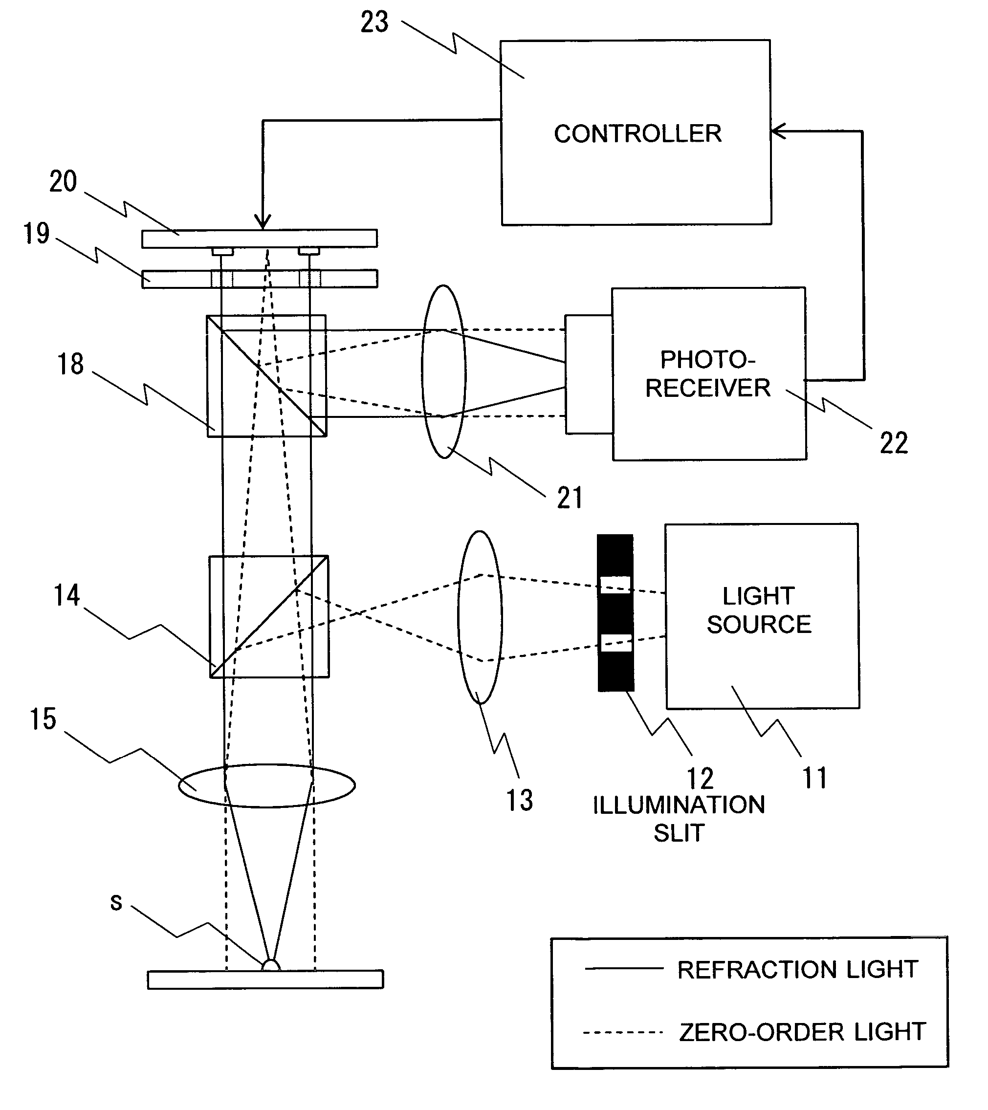
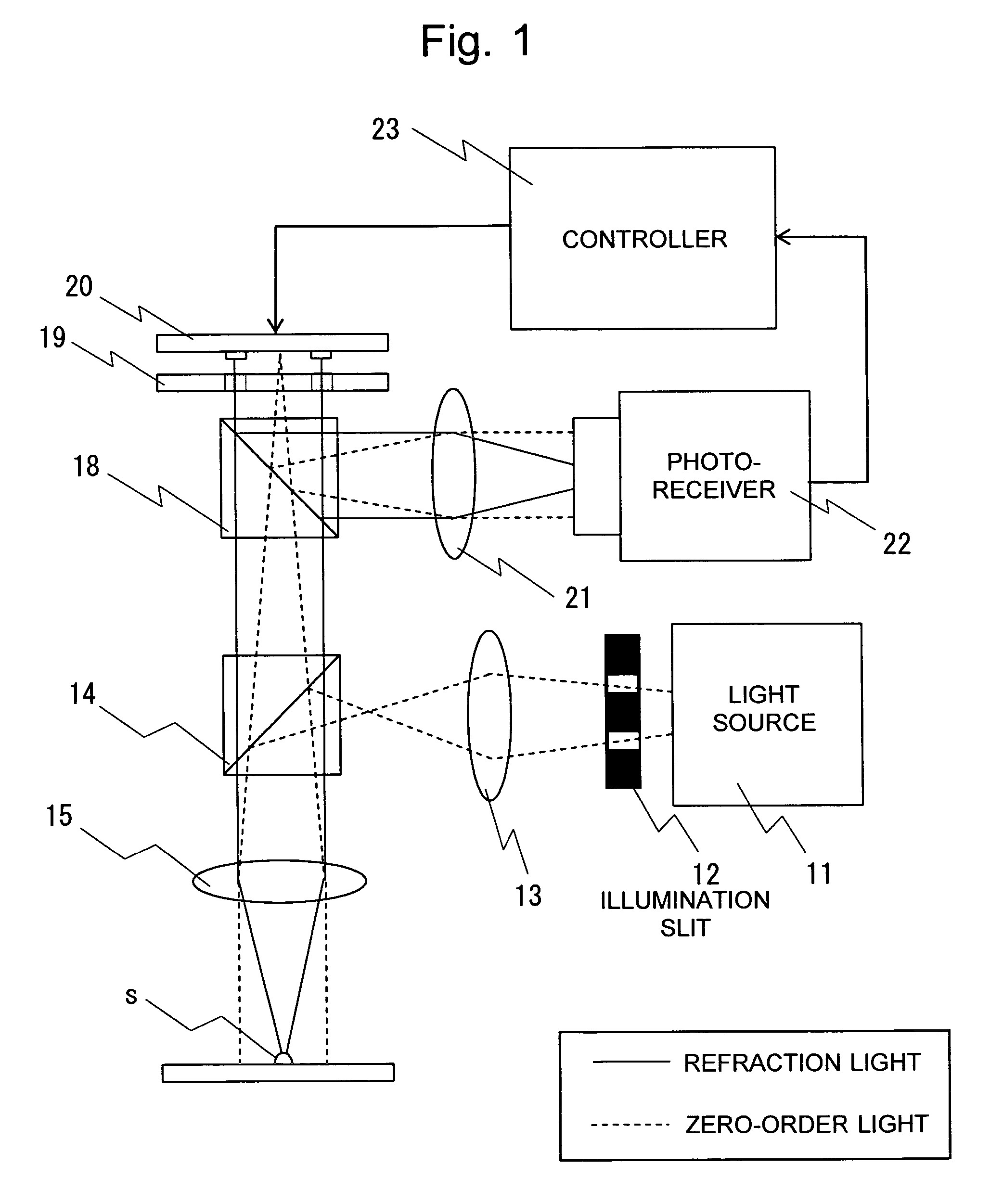
[0062]FIG. 1 shows the general construction of an embodiment of the three-dimensional geometric measurement system according to the present invention. The light emitted from the white light source 11 passes through the ring-shaped illumination slit 12 to form a ring of illumination light, called the “annular illumination light.” The annular illumination light passes through the lens 13 and is reflected by the half mirror 14 to the downward direction in the drawing. The reflected light is converged by the lens 15 onto the target object (phase object) s.

[0063] When the light cast onto the target object s is reflected by its surface, the phase of the light changes according to the geometry of the object s (i.e. the height of the object in the light-casting direction). With the phase thus changed, the reflected light passes through the lens 15 again, and then through the half mirror 14, to reach the half mirror 18 located above. The half mirror 18 splits the reflected light into two op...


PUM

PropertyMeasurementUnit
widthaaaaaaaaaa
strengthaaaaaaaaaa
optical probeaaaaaaaaaa

Abstract

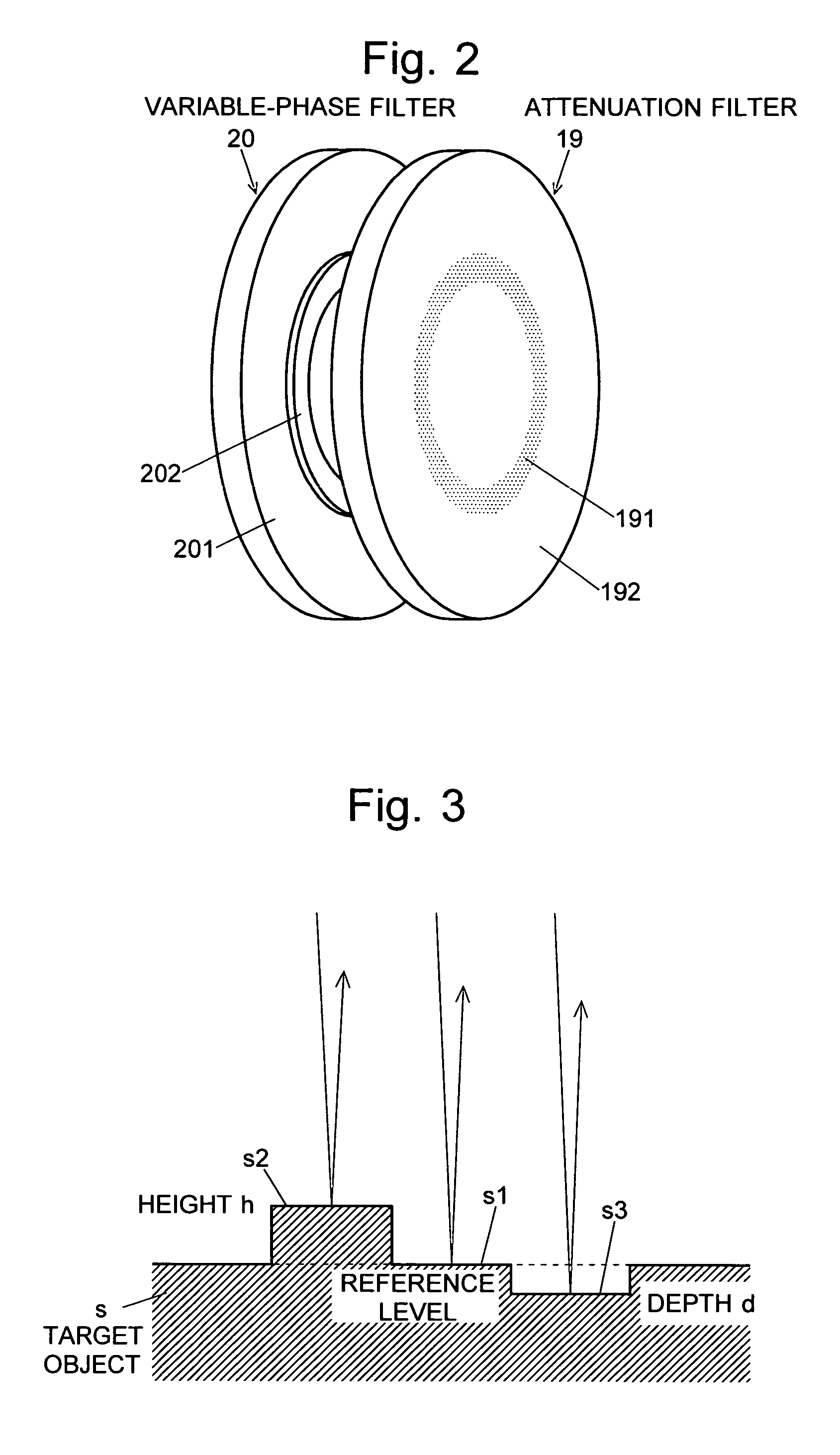
The present invention intends to provide a measurement system capable of measuring a three-dimensional geometry of a target object over a relatively large area, in a small length of time and by a contact-free method. When a ray of light is cast from a light source onto the target object s and reflected at a certain point on the surface of the target object s, the light produces direct reflection light (zero-order light) and higher-order diffraction light. The zero-order light is guided by a separating optics to a movable reflector of a variable-phase filter 20 while the higher-order diffraction light is guided to a fixed reflector. The two rays of light are reflected by the corresponding reflectors and led to substantially the same point by an interference optics system. At this point, the two rays of light interfere with each other. Under such a condition, when the movable reflector of the variable-phase filter 20 is moved, the strength of the interference light at the imaging point of the interference optics system gradually changes. The position of the movable reflector at the peak point of the interference light depends on the distance between the starting point on the target object s and the movable reflector. Therefore, the position of the starting point can be calculated from the position of the movable reflector at the peak point. By performing such a measurement and calculation process on each point of the image of the target object, one can determine the three-dimensional geometry of the object. Moreover, each point can be analyzed by Fourier-transforming the interferogram of that point into a spectrum.

Description

TECHNICAL FIELD [0001] The present invention relates to a technique for analyzing and measuring the three-dimensional geometry of a target object, which uses an optical probe to quickly and easily measure the three-dimensional geometry of objects having various sizes from nanometers to micrometers, and which is capable of performing an analysis of an object. BACKGROUND ART [0002] Development of the next generation semiconductor devices is a critical national project for the Japanese semiconductor industry in order to compete with those of the United States and other countries and provide basic support for further developments of the information technology (IT) industry. Success in the development of the next generation semiconductor devices hinges on the establishment of techniques for manufacturing and checking hyperfine structures of nanometers or smaller (0.1 μm or smaller in wire width). [0003] Also, the recent increase in the number of transistors per chip requires a multilayer...

Claims


Application Information

Patent Timeline
Patent Type & Authority Applications(United States)
IPC IPC(8): G01B11/02G01N21/27G01B11/24
CPCG01B11/2441
Inventor ISHIMARU, ICHIROUHYODO, RYOJI
Owner TECHNO NETWORK SHIKOKU
Learn More