Heat dissipating element for a memory

a heat dissipating element and memory technology, applied in the direction of cooling/ventilation/heating modification, semiconductor/solid-state device details, semiconductor devices, etc., can solve the problems of memory damage, lack of how to enable the heat dissipating device to be more solid,

Inactive Publication Date: 2007-06-14
LO RUEI AN
View PDF10 Cites 7 Cited by
  • Summary
  • Abstract
  • Description
  • Claims
  • Application Information

AI Technical Summary

Benefits of technology

[0007] Accordingly, the primary object of the present invention is to provide a heat dissipating element for a memory, which includes a set of fins that can be latched oppositely, and a hook member which enables the fins to be more solid after being latched, wherein the set of fins are latched by inserting a T-shape hook plate into a T-shape slot, thereby achieving a purpose that the fins will not easily get loose after being assembled.
[0008] Another object of the present invention is to provide a heat dissipating element for a memory, wherein shear sides of perforations on the hook member are formed by pressing slant press pieces located on the fins and extended downward, after clipping the fins with the hook member, such that the fins will not be shaken and loosened by an external force, after being assembled.
[0009] Still another object of the present invention is to provide a heat dissipating element for a memory, wherein ribs which are extended outward are located at lower edges of fins, such that the fins will be deformed adequately when the ribs are pressed, thereby facilitating the press pieces to be separated from the perforations.

Problems solved by technology

However, for a computer which is often moved, the fins are memory to be damaged due to a lack of efficient heat dissipation from a long term of usage, by using this kind of method of locking with the rivets.
However, although the aforementioned two patents are an improvement to conventional drawbacks that the device cannot be latched quickly or cannot effectively prevent from a dust, they are still in lack of how to enable the heat dissipating device to be more solid without easily getting loose or to be quickly separated, after being assembled, which is a pity.

Method used


Image

  • Heat dissipating element for a memory
  • Heat dissipating element for a memory
  • Heat dissipating element for a memory

Examples


Embodiment Construction

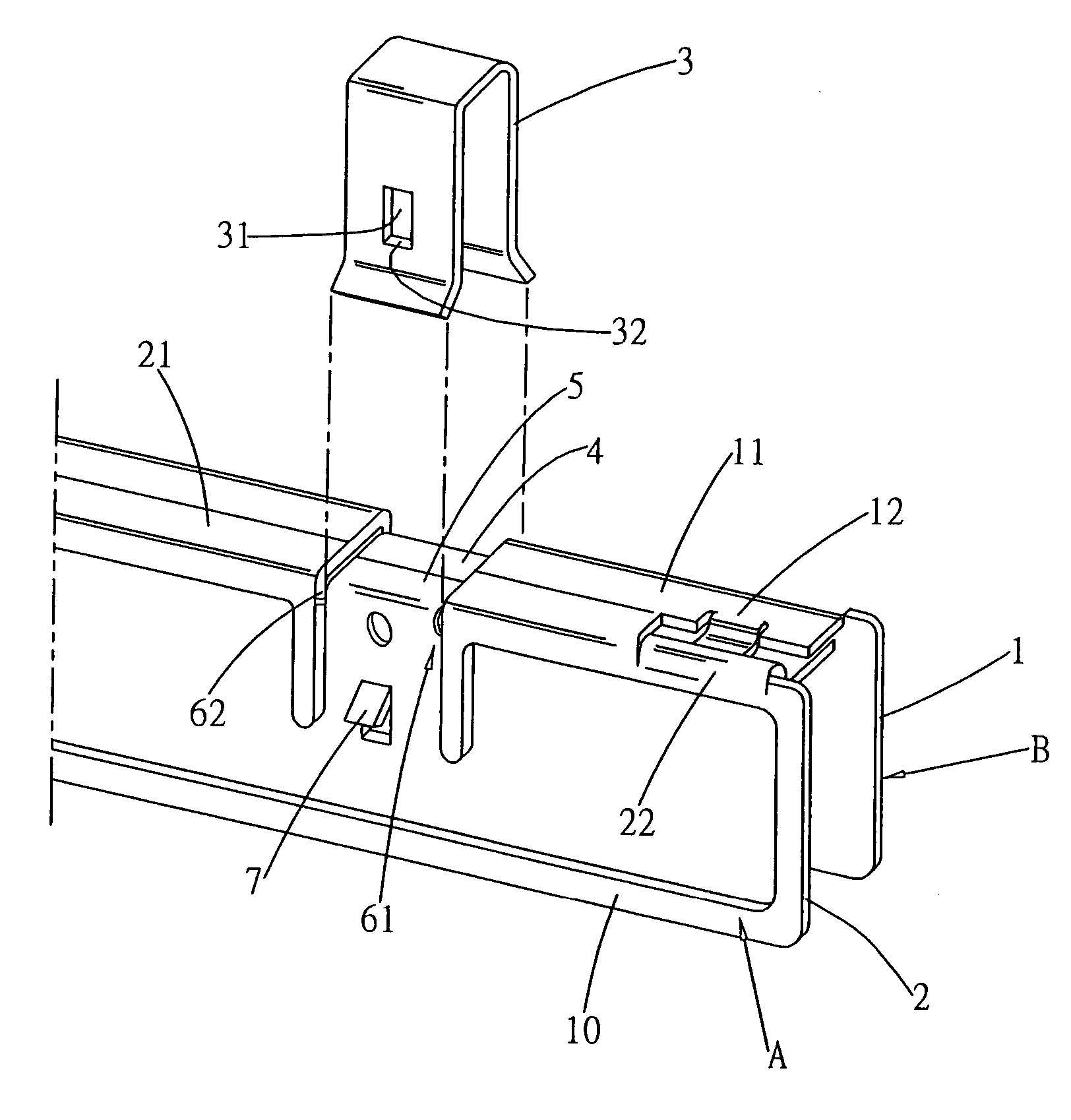
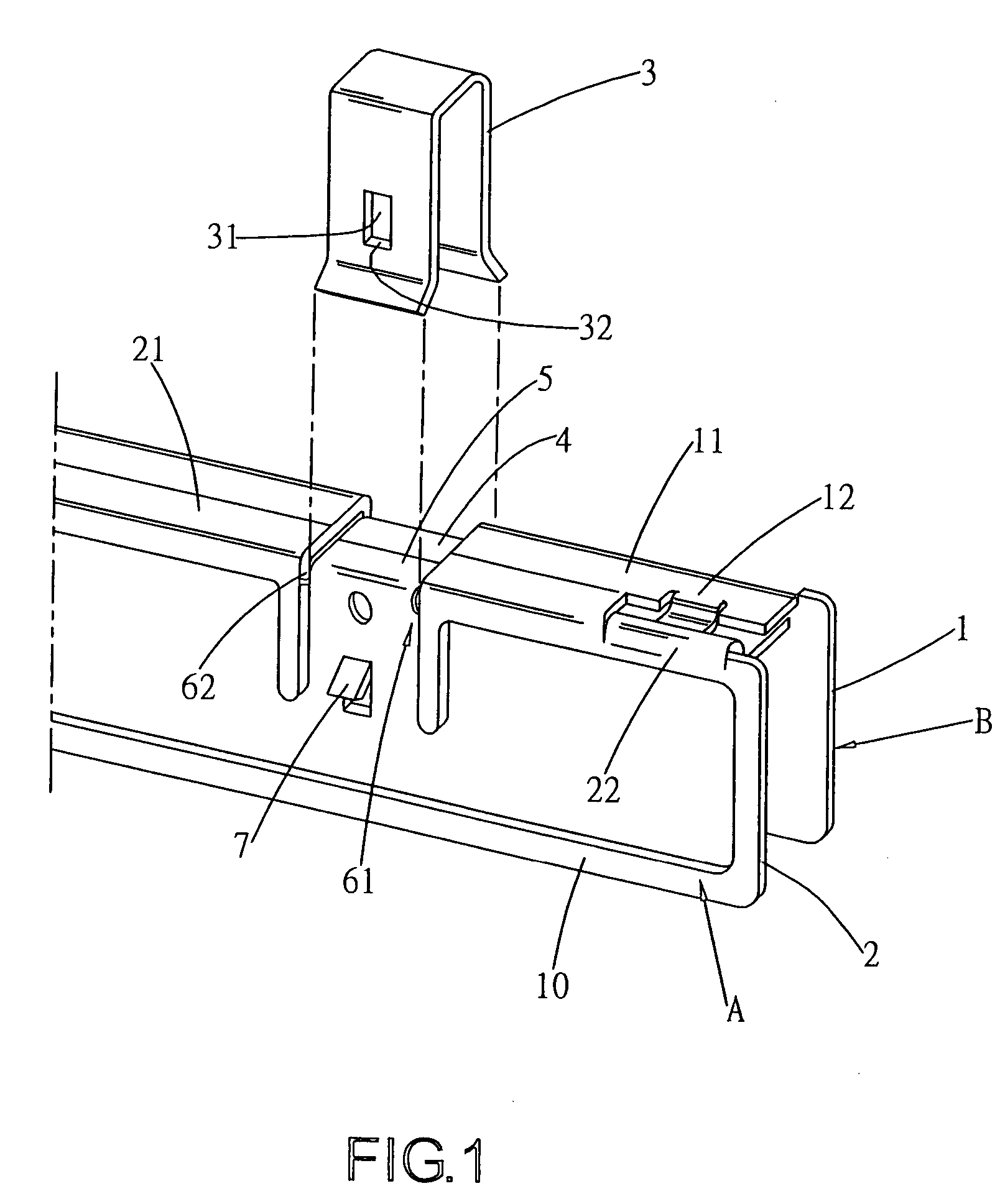
[0017] Referring to FIG. 1 and FIG. 2, a heat dissipating element of the present invention includes a set of fins 1, 2 which can be latched oppositely, and a hook member 3, wherein the fins 1, 2 are connected to a memory with heat conducting plates 10, and the top ends of fins 1, 2 are provided with connection plates 11, 21 which are bended toward each other. At two ends of connection plates 11, 21, insertion parts 12 and hook parts 22 are located at positions corresponding to each other. One end of the insertion part 12 is connected with the connection plate 11, and the other end is extended toward a front at a height slightly lower than that of the connection part 11. Horns 131, 132 are protruded at two sides of an end of insertion part 12 that is extended toward a front, thereby forming a T-shape hook plate 13. An end of the hook part 22 is connected with the connection plate 21 with an arc shape neck 23, such that an adequate space 24 is reserved between the neck 23 and the fin ...


PUM


Abstract

A heat dissipating element for a memory is composed of a set of fins which can be latched oppositely, and a hook member which can be used to clip the set of fins, wherein the aforementioned fins are hooked with a T-shape hook plate having horns and a T-shape slot having through-holes and a through-hole at its neck. The hook member is provided with perforations on its surfaces, and slant press pieces which are extended downward are located on surfaces of fins. After the fins are clipped by the hook member, the hook member is hooked with the slant press pieces through the shear sides below the perforations. In addition, lower edges of the aforementioned fins are provided with slant ribs extended outward, and by pressing the ribs, the aforementioned slant press pieces can be separated from the perforations of hook member.

Description

BACKGROUND OF THE INVENTION [0001] (a) Field of the Invention [0002] The present invention relates to a heat dissipating element for a memory, and more particularly to a heat dissipating element which is assembled at an exterior of memory, is not easily getting loose, and can be exchanged conveniently after being assembled. [0003] (b) Description of the Prior Art [0004] The heat dissipating problem for interior elements of a computer has always been an object to be solved and improved by related industries. In order to prevent an element such as a central processing unit (CPU), an integrated circuit (IC), a power transistor, and a memory from being overheated due to a long term of usage, thereby affecting its quality, a general method is to add a heat dissipating element onto an exterior of the element. [0005] In terms of the heat dissipating element for a memory, two pieces of fins, along with two pieces of heat conducting plastic plates, were previously used to enclose the memory,...

Claims


Application Information

Patent Timeline
Patent Type & Authority Applications(United States)
IPC IPC(8): H05K7/20
CPCH01L23/4093H01L2924/0002H01L2924/00
Inventor LO, RUEI-AN
Owner LO RUEI AN
Why Eureka
Try Eureka