
Internal air-exchange spring brake chamber

Inactive Publication Date: 2007-06-14
SORL AUTO PARTS
View PDF15 Cites 22 Cited by
  • Summary
  • Abstract
  • Description
  • Claims
  • Application Information

AI Technical Summary

Benefits of technology

[0011] The spring brake chamber assembly also includes a sealing member positioned in the central opening of the adapter member through which the second end portion of the piston rod passes and adapted for preventing air from flowing through between the pressurized chamber and the ventilation chamber, where the sealing member comprises one or more O-ring seals.
[0012] The spring brake chamber assembly may further include a valve mounted onto the second end portion of the piston rod for operably controlling the flow of air through the air passageway between the breathing chamber and the ventilation chamber. The valve is configured such that as the power spring moves from the retracted toward the extended position, compressed air is introduced to the breathing chamber from the ventilation chamber through the air passageway; as the power spring moves from the extended position toward the retracted position, compressed air is introduced from the breathing chamber to the ventilation chamber through the air passageway; and when the power spring is in the retracted position, compressed air is prevented from flowing from the ventilation chamber to the breathing chamber through the air passageway.
[0017] In one embodiment, the flow control member is configured such that as the power spring moves from the retracted toward the extended position, compressed air is introduced to the breathing chamber from the ventilation chamber through the air passageway; as the power spring moves from the extended position toward the retracted position, compressed air is introduced from the breathing chamber to the ventilation chamber through the air passageway; and when the power spring is in the retracted position, compressed air is prevented from flowing from the ventilation chamber to the breathing chamber through the air passageway.

Problems solved by technology

However, dirt, moisture and other unwanted material and contaminants such as salt from the outside environment may enter into the spring chamber through these openings, which may cause the corrosion of the compression spring and therefore reduce the lifetime of the spring brake.
However, these arrangements require extra components and complex machining of the components.
However, the use of the external filters requires additional space, components, machining and assembly effort.
Therefore, a heretofore unaddressed need exists in the art to address the aforementioned deficiencies and inadequacies.

Method used


Image

  • Internal air-exchange spring brake chamber
  • Internal air-exchange spring brake chamber

Examples


Embodiment Construction

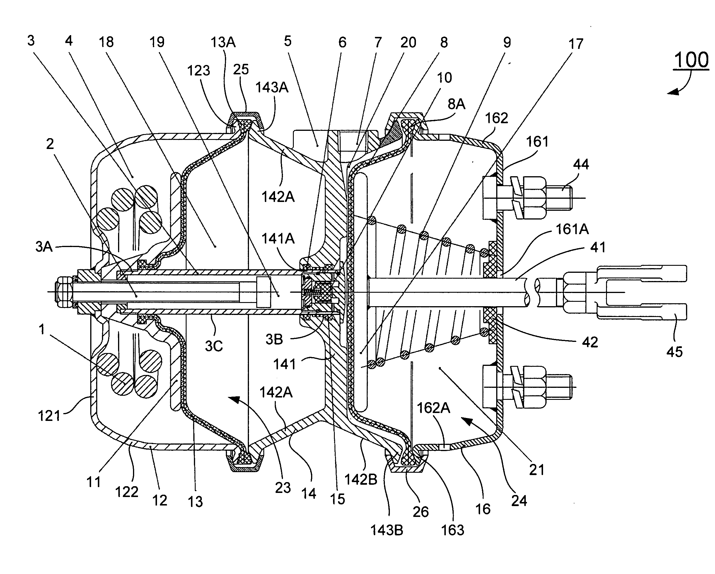
[0023] The present invention is more particularly described in the following examples that are intended as illustrative only since numerous modifications and variations therein will be apparent to those skilled in the art. Various embodiments of the invention are now described in detail. Referring to the drawings, like numbers indicate like components throughout the views. As used in the description herein and throughout the claims that follow, the meaning of “a”, “an”, and “the” includes plural reference unless the context clearly dictates otherwise. Also, as used in the description herein and throughout the claims that follow, the meaning of “in” includes “in” and “on” unless the context clearly dictates otherwise.

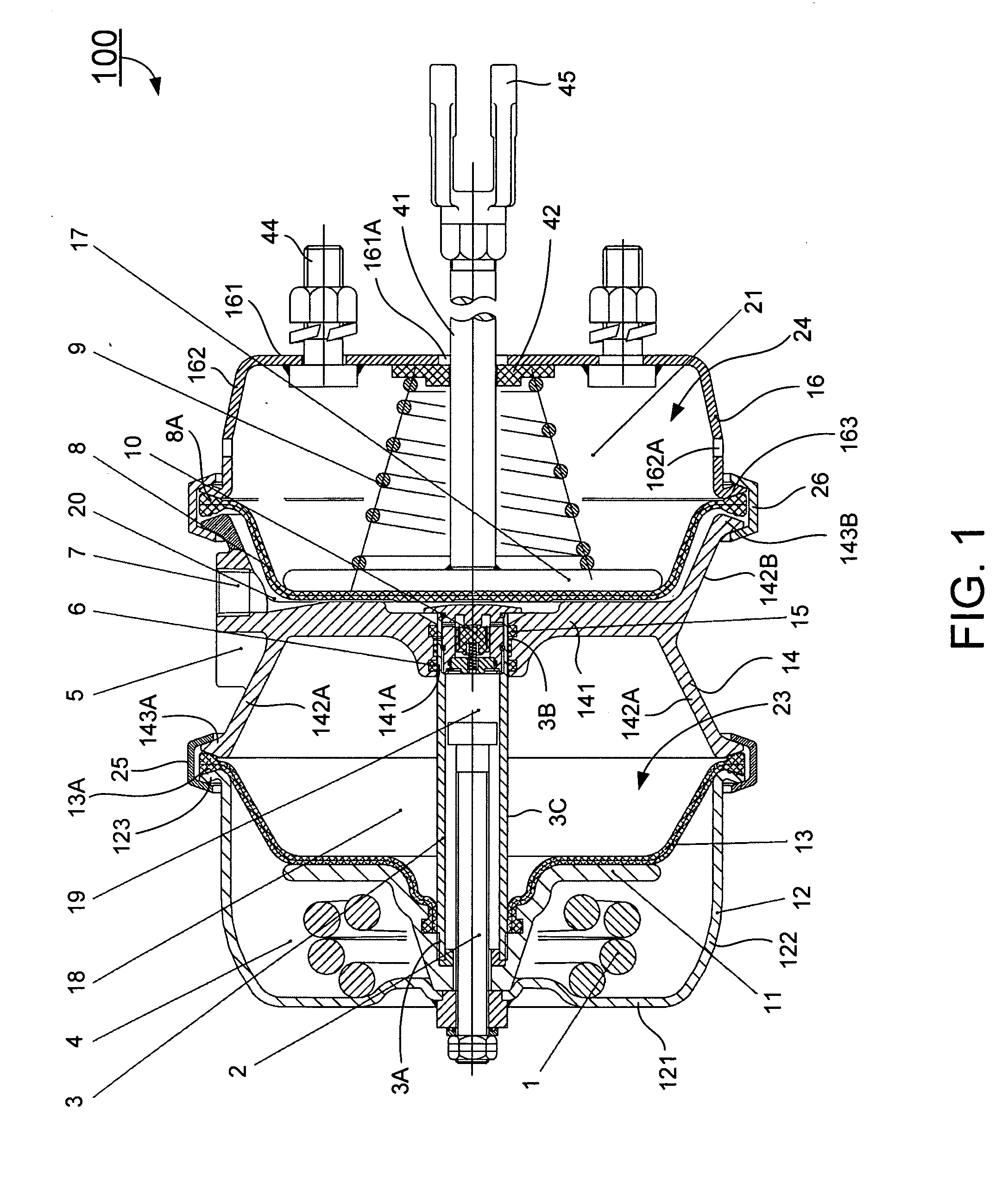
[0024] The description will be made as to the embodiment of the present invention in conjunction with the accompanying drawing of FIG. 1. In accordance with the purposes of this invention, as embodied and broadly described herein, this invention, in one aspect, relates ...


PUM


Abstract

A spring brake chamber assembly. In one embodiment, the spring brake chamber assembly includes a housing having a first housing and a second housing separated by a divider wall, each of the first housing and the second housing having a wall; a first diaphragm configured to be positioned in the first housing to divide the first housing into a breathing chamber and a pressurized chamber, and reciprocally movable therein between a first position and a second position in response to the introduction and / or exhaustion of compressed air to the pressurized chamber; a second diaphragm configured to be positioned in the second housing to divide the second housing into a ventilation chamber and a brake chamber, and reciprocally movable therein between a first position and a second position in response to the introduction and / or exhaustion of compressed air to the ventilation chamber; and a flow control member passing through the pressurized chamber and extending between the breathing chamber and the ventilation chamber for selectively controlling the flow of air between the breathing chamber and the ventilation chamber, where the wall of the breathing chamber is sealed such that no air directly flows through between the breathing chamber and the atmosphere, and the breathing chamber is in fluid communication with the ventilation chamber through the flow control member.

Description

CROSS-REFERENCE TO RELATED APPLICATION [0001] This application claims priority of Chinese Patent Application No. 200520142949.1, filed on Dec. 12, 2005, entitled “INTERNAL AIR-EXCHANGE SPRING BRAKE CHAMBER” by Chuanwu Li and Weijun Deng, the disclosure of which is incorporated herein by reference in its entirety. FIELD OF THE INVENTION [0002] The present invention is generally related to a brake, and, more particularly, is related to a spring brake chamber assembly having a network of air chambers with an internally breathing mechanism for regulating the flow of air within the network of air chambers. BACKGROUND OF THE INVENTION [0003] Spring brakes are widely utilized in the automotive industry. A spring brake typically includes a brake actuator assembly actuated by the selective application of a fluid such as compressed air in a network of chambers. A brake actuator typically has both a service brake actuator housed in a service brake chamber for actuating the brake under normal d...

Claims


Application Information

Patent Timeline
IPC IPC(8): B60T13/04
CPCB60T17/083
Inventor LI, CHUANWUDENG, WEIJUN
Owner SORL AUTO PARTS
Learn More