External wearable light therapy treatment systems

a technology of wearable light and treatment system, which is applied in the field of external wearable light therapy treatment system, can solve the problems of not providing sufficient energy to the target for effective treatment, and the device is not suitable for self-administered light therapy, so as to improve the ability of light to reach and expand the joint

Inactive Publication Date: 2007-06-07
LIGHT SCI ONCOLOGY
View PDF36 Cites 270 Cited by
  • Summary
  • Abstract
  • Description
  • Claims
  • Application Information

AI Technical Summary

Benefits of technology

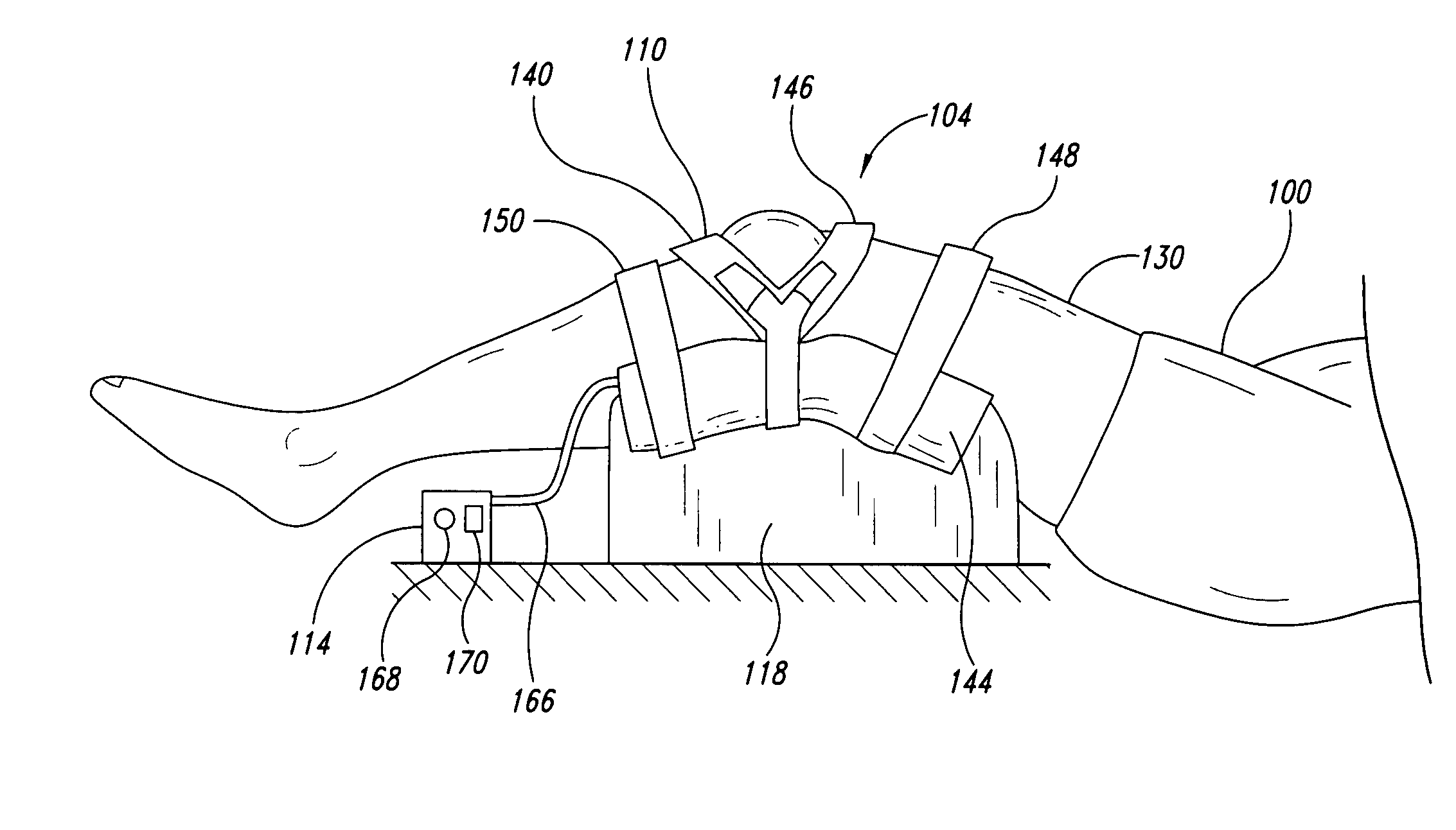
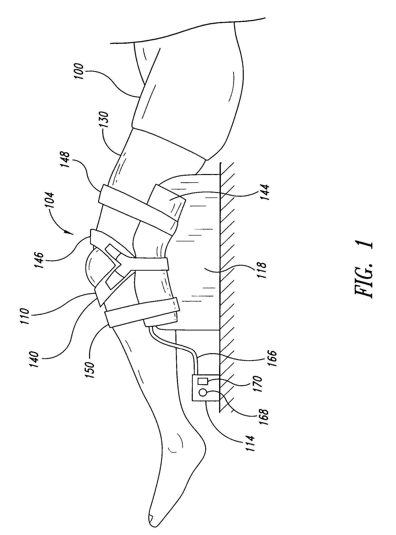
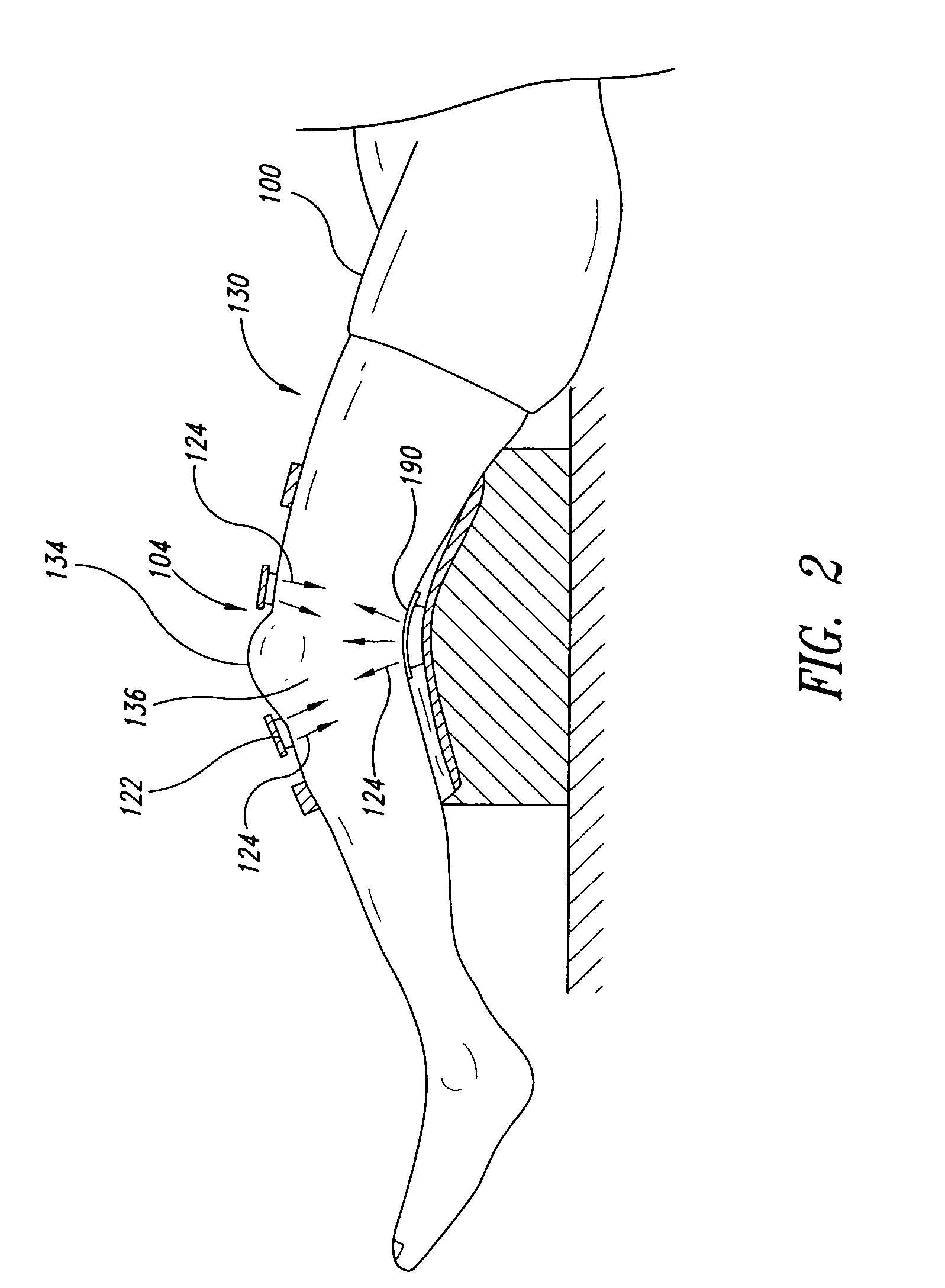
[0006] In one embodiment, this problem is resolved by providing a structure that accommodates a joint of the subject or end user as a self-locating feature, to correctly position an array of lights sources for providing light therapy, for example, for pain relief. The structure may be sized, shaped and / or dimensioned to receive the joint when the joint is partially or fully bent or articulated. Bending the joint (e.g., knee) slightly may also expand the joint and improve the ability of the light to reach the targeted areas. In addition, this allows the targeting of the synovium, a novel target for light therapy for joint pain.
[0011] Optionally, a light reflective layer disposed over an outwardly facing surface of the flexible substrate is provided to reflect light emitted by the light sources back toward the treatment site. Also, an optically transparent coating is preferably applied over the plurality of light sources mounted on the flexible substrate to provide protection.
[0017] In some embodiments, a light therapy treatment system comprises a power source and a wearable positioning structure. The positioning structure is configured to receive a body part and to engage at least one anatomical feature of the body part so as to position itself with respect to the body part. A light emitting system is coupled to the power source. The light emitting system is positioned relative to the positioning structure such that, when the body part is received by the positioning structure and the light emitting system receives energy from the power source, the light emitting system is positioned (e.g., due to engagement between the positioning structure and the at least one anatomical feature) to deliver a therapeutically effective amount of light to a target site in the body part.
[0021] In some other embodiments, a method of providing light therapy to a joint of a subject is provided. The method includes placing a joint having arthritis in proximity to a wearable therapy treatment system and delivering a dose of high intensity light to the joint. The dose comprises a therapeutically effective amount of high intensity light to substantially inhibit progression of at least one condition associated with arthritis. In some embodiments, the at least one condition can include, without limitation, discomfort, pain, inflammation, warmth, or cartilage damage or destruction. In some embodiments, the therapeutically effective amount of high intensity light substantially prevents or reverses the progression of at least one condition associated with arthritis.
[0027] Light therapy, however, can involve treatment agents, e.g., photosensitive agents, energy activated agents, and / or drugs and compounds to specific target cells or compositions of a subject or patient. Light or non-light energy (e.g., ultrasonic energy) at a relatively low intensity rate can be administered over a prolonged period of time in order to activate these agents. These sources may achieve maximal cytotoxicity with minimal side effects.

Problems solved by technology

Light therapy devices often have very localized light sources that require precise positioning, thus requiring placement by highly-trained personnel.
These types of devices are not suitable for self-administered light therapy by the average user because it is often difficult to ensure proper compliance, and the average user is not properly trained to administer light therapy.
Other types of light devices, such as “light blankets,” do not require accurate placement, but they do not provide sufficient energy to the target for an effective therapeutic treatment.

Method used


Image

  • External wearable light therapy treatment systems
  • External wearable light therapy treatment systems
  • External wearable light therapy treatment systems

Examples


Embodiment Construction

[0076] In the following description, certain specific details are set forth in order to provide a thorough understanding of various disclosed embodiments. However, one skilled in the relevant art will recognize that embodiments may be practiced without one or more of these specific details, or with other methods, components, materials, etc. In other instances, well-known structures associated with light delivery devices, control circuits, power regulators and / or light emitting sources, for example incandescent light sources or light emitting diodes have not been shown or described in detail to avoid unnecessarily obscuring descriptions of the embodiments.

[0077] Unless the context requires otherwise, throughout the specification and claims which follow, the word “comprise” and variations thereof, such as, “comprises” and “comprising” are to be construed in an open, inclusive sense, that is as “including, but not limited to.”

[0078] Reference throughout this specification to “one embo...


PUM


Abstract

A light therapy system provides for self-alignment or positioning with respect to a joint of a subject. The light therapy system can provide light therapy to a body part of a subject. The therapy system has a main body configured to be placed adjacent a target site and an activatable light emitting system is coupled to the main body. The light emitting system is capable of delivering a therapeutic amount of light energy to the target site when the main body is placed adjacent the target site.

Description

CROSS-REFERENCE TO RELATED APPLICATION [0001] This application claims the benefit under 35 U.S.C. § 119(e) of U.S. Provisional Patent Application No. 60 / 728,556, filed Oct. 20, 2005, where this provisional application is incorporated herein by reference in its entirety.BACKGROUND OF THE INVENTION [0002] 1. Field of the Invention [0003] This disclosure is generally related to medicinal or therapeutic treatment systems, and more particularly to external wearable light therapy treatment systems. [0004] 2. Description of the Related Art [0005] Light therapy devices that are intended for home-use typically require the user to accurately position the device, particularly for joint treatments. Light therapy devices often have very localized light sources that require precise positioning, thus requiring placement by highly-trained personnel. These types of devices are not suitable for self-administered light therapy by the average user because it is often difficult to ensure proper complian...

Claims


Application Information

Patent Timeline
IPC IPC(8): A61N5/06
CPCA61B2017/00057A61B2017/00084A61B2019/465A61N5/0613A61N5/062A61N2005/0629A61N2005/0645A61N2005/0647A61N2005/0652A61B2090/065
Inventor ROBINS, ANTHONY J.BURWELL, PHILLIPSHINE, DAVID B.CHEN, JAMES C.
Owner LIGHT SCI ONCOLOGY
Why Eureka
Try Eureka